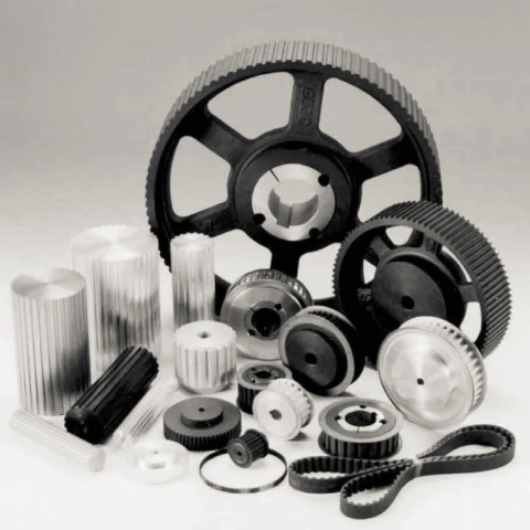
V- belt pulley of different kinds . The material used is certainly cast iron , and for only a few types it is metal. They have a little prebore which can be machined according to clients’ requirements. Furthermore the most typical types can be found as well with taperlock bore.
PRECISON CASTING LOST WAX CASTING STAINLESS STEEL HAND POLISHED PULLEY
Industrial parts, Machinery parts, construction parts, valve parts, pump parts, impeller parts, train ,craft, hydraulic pressure, Agricultural machinery, Marine hardware, Auto parts, energy fittings, food machinery, harness fittings, machinery parts
CAST IRON TIMING BELT PULLEY (3M, 5M, 8M, 14M, XL, H, L)
Our main goods include: European pulley, American pulley, Couplings, taper bushing, QD bush, lock element, adjustable motor base, engine rail, sprockets, chain, bolt on hubs, weld on hubs, jaw crusher gear & spare parts and a myriad of nonstandard Casting products etc.
OEM Grey Iron Sand Casting Tractor Parts Belt Pulleys
We hereby introduce our organization as a leading company of Machinery parts in china, we mainly doing casting parts, forging parts, plastic material injection parts, stamping parts and machining parts. various products rely upon our big factory who had over twenty years history and encounter. and we are most proficient at OEM and CNC according buyer drawing or design.
Ever-power specialist to make all types of mechanical transmitting and hydraulic transmission like
planetary gearboxes, worm reducers, in-line helical gear speed reducers, parallel shaft helical equipment reducers, helical bevel reducers, helical worm gear reducers, agricultural gearboxes, tractor gearboxes, car gearboxes, pto get shafts, special reducer
More Product
related gear components and various other related products, sprockets, hydraulic system, vaccum pumps, fluid coupling, gear racks, chains, timing pulleys, udl speed variators, v pulleys, hydraulic cylinder, gear pumps, screw air compressors shaft collars low backlash worm reducers and so forth. furthermore, we are able to produce custom-made variators, geared motors, electric motors and various other hydraulic items according to consumers’ drawings.
Correct belt installation can be extremely important with regards to getting optimum life and efficiency from your belts. Remember to be certain that your belt pulleys happen to be properly prearranged with a straight edge and that they are not worn and cutting into the belts. Proper belt pressure should be established with a belt stress tool that can also be purchased on-line and reset again following the first week or so of operation to allow for belts that stretch, and all belts will extend. The majority of the stretching takes place in first time of operation so it is vital to re examine vbelt tension after the belt has had some run time.
This technique operates to either reduce or increase speed or torque, and for power transmission between shafts, especially those which are not axially aligned. Both of these complement one another wherein the belt balances the load while the pulley settings the speed. Focusing on how they work will help you take benefit of their functions in boosting motor performance, and at exactly the same time, assist you to choose types that are as well cost-efficient.
Right now, there are a great number of belts available in the market that you can simply get your hands on. It would be an excellent help to know the elements that will assist you decide what sort of belt to work with. A number of the features that you have to look for in belts will be their advanced of productivity and, as well, low level of maintenance. Another thing to consider may be the optimum load and the initial pressure of the belt. You will find a limit to the load size prior to the belt slips and the original tension plays a large role in identifying this factor. Too little initial tension can lead to a dead battery and the alternator belt slipping. However, an excessive amount of initial tension will lead to wear and tear of the belts and bearings.
Among the most popular belt drivers will be the V-belts. Their wedge action can produce a lot of friction and boost the power transmission capacity. They have an estimated 5% reduction and 93% efficiency. Alternatively, if you are buying a belt program to work greatest with a vehicle, you then have to have the synchronous belt. It is also referred to as timing belt pulley that may control the starting and closing of engine valves. If you are looking for toothed-belts that need little protection and re-tensioning, then your belt pulley is usually your best choice. In addition, they are the most effective, can run slip-free, and can job both in wet and oily environment.
With regards to v-belts their’s more to merely throwing them on and walking aside. Unfortunately generally that is exactly what is done. Another misconception is certainly that v-belts need not be replaced until they have completely broken and will not function at all. V-belts will stretch and begin slipping long before they’ll break. V-belt dressing will buy you some short term time but is not the answer. An excellent preventive maintenance program may include quickly replacing vbelts every six months according to equipment run time.
silica sol expenditure casting,Sodium Silicate sand casting,Sodium Silicate expense casting, lost-wax expense casting, clay sand casting, furan resin sand casting, shell Casting, die casting
Taper bush pulley and sound hub pulley, various quickness pulley, smooth belts pulley, adjustable swiftness v belt pulley, materials is gray cast durability, iron plus they have good hardness.
For American normal pulley, they are suited to 3L,4L,5L,A,B,C,3V,5V,8V belt, after precise machining and ability painting ,they will get smoonth and beautiful area ,and good anticorrosive capacity
Significant Gray Iron Casting Belt Steering wheel Pulley can be produced by casting. Prevalent used material is certainly GG25 or other custom-made material.
Strictly quality inspection system can produce top quality products. Our top quality documentation system is ISO 9001:2015. For each order,we provides report for material chemical components testing,UT tests,hardness, mechanical property assessment(impact testing,yield power testing,tensile strength assessment),size inspection,etc.
Metal Parts Remedy for Vehicle, Agriculture equipment, Construction Machine, transportation equipment, Valve and Pump program, Agriculture machine steel Parts, engine bracket, vehicle chassis bracket, gear box , gear housing , gear go over, shaft, spline shaft , pulley, flange, connection pipe, pipe, hydraulic valve, valve casing ,Fitting , flange, wheel, fly wheel, oil pump housing, starter housing, coolant pump housing, transmitting shaft , transmission equipment, sprocket, chains etc.
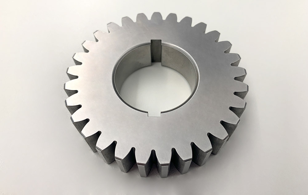
V- belts pulleys change from timing belt pulleys for the type of belt ( V-section) they fit in. HZPT provides in stock a wide selection of V- belt pulley of different kinds ( according to type and width of belts). The material used is normally cast iron EN-GJL-250 UNI EN 1561, and for only a few types it really is steel C45 E UNI EN 10083-1. They possess a small prebore that can be machined regarding to customers’ requirements. Moreover the most common types are available also with taperlock bore.
Catalog of V Taper Lock pulleys(European Normal Taper bore)SPA, SPB, SPC, SPZCatalog of Smooth Belt Pulleys for Taper Bushes (European Normal)Catalog of Adjustable V Taper Pulleys(Euroepan Regular)Catalog of sheavesSheaves for 3L, 4L, A, 5L and B beltsAK, AKH, 2AK, 2AKH, BK, BKH, 2BK, 2BKH, 3BK, 3BKH
Metal Parts Alternative for Vehicle, Agriculture equipment,, transportation apparatus, Valve and Pump system, Agriculture machine metal Parts, engine bracket, vehicle chassis bracket, gear package , gear housing , valve go over, etc.
Film belts tend to be classified as a variety of smooth belt, but actually they certainly are a individual type. They contain a very thin belt (0.5-15 millimeters or 100-4000 microns) strip of plastic and occasionally rubber. They are generally intended for low-vitality (10 hp or 7 kW), high-speed uses, allowing high proficiency (up to 98%) and extended life. These are seen in business devices, tape recorders, and various other light-duty operations.They are length adjustable by disassembling and removing links when needed.
WORM GEAR
Manufacturer supplier exporter of worm gear
We warmly welcome clients each at home and abroad to get hold of us to negotiate business, exchange data and cooperate with us.
We specializing during the manufacturing of Agricultural Gearbox, PTO Shafts, Sprockets, Fluid Coupling, Worm Gear Reducers, Gears and racks, Roller Chains, Sheave and Pulleys, Planetary Gearboxes, Timing Pulleys, Shaft Collars and more.
Consist of 1 0.5 modulus brass worm gear shaft and a single twenty teeth brass worm gear wheel.
The transmission framework of worm shaft is simple, compact, small volume and light weight.
Worm Shaft Z1=1, flip a round of worm gear teeth, can get a sizable transmission ratio, typically from the power
CAST IRON WORM GEAR REDUCER
The transmission is steady, the vibration, impact and noise are compact, the reduction ratio is huge, the versatility is broad, and it could be utilized with many mechanical gear.
It can obtain a substantial transmission ratio with single-stage transmission, and has a compact structure. Most models have greater self-locking efficiency, and will save braking products for mechanical tools with braking demands.
Gears aids us through a mechanism of rotation among two axes to make energy. Consequently they, with the help of rotation following a mechanical concept relevant to physics transfers pace into electrical power. They could be of two sizes, one smaller as well as the other massive, adjoining one another with all the enable of teeth. The teeth are interlocked and cause rotation.
WORM GEAR AND Benefits OF WORM GEARS
If among two gears one particular is heavier and also the other lighter it’s mentioned the bodyweight gets to be the terrific aspect to cause friction. If your excess weight looks also heavy rotation could possibly be hampered resulting in inconvenience to move the machine with which these are attached.
Unique gears have different teeth. The teeth are in a twisted kind or in the straight form. It’s the action of a helical a single to radiate motion among two shafts. Whereas the bevel form has teeth depending on conical surface. The shafts are never ever parallel and intersected sharply in an angle.
WORM GEAR Pace REDUCER Field Pace REDUCER FOR Electrical MOTOR
Two or 3 reducers may be used to kind a multi-stage reducer to acquire a great gear ratio.
A worm, in industrial parlance, is actually a shaft that has a helical thread. It is actually usually a part of the gear that meshes using a toothed wheel. Worm gears on the other hand, are those acknowledged as worm wheels. Sometime quite a few individuals are puzzled with the terms worm, worm gear and worm drive, pondering that these 3 suggest precisely the same issue.
Worm gears are crucial particularly when there exists a need to cut back the gear dimension. It’s the worm which has the capability to produce the gear rotate and not another way about. With the shallow angle to the worm, the gear will not possess the capability to rotate it.
Varieties of worm gear
There are actually basically 3 unique sorts of worm wheels: the non-throated; single throated; and double throated. Non-throated worm wheels are these that don’t have throats in both the worms as well as the gear. Single throated classes are these whose gears are throated. Lastly, double throated ones are people with throated worms and gears.
Worm gear traits
You will discover notable traits of the worm wheel. Initially, it’s the capability to transfer and carry load with utmost accuracy. Additionally it is most effective for big velocity reductions. The efficiency from the worm gear, nevertheless, depends upon installation ailments, the worm’s lead angle, sliding velocity, surface high quality and lubricant selection.
Producing worm gears come to be powerful
A process recognized as double enveloping makes worm gearing become far more effective. This technologies enhances the existing options of your worm wheel. This prospects to better accuracy and enhanced torque. What helps make the procedure so particular is definitely the proven fact that it could be made use of to produce improved lubrication and style though loads are divided in each and every from the gear’s teeth.
Worm gear applications
Worm wheels make conveyor systems do its perform. Conveyors are tools to transfer one materials from one place to another. Aside from conveyor programs even though, the worm wheel may also be used in large effectiveness cars.
Carbon Steel And Stainless Steel Conveyor Chain Hollow Pin Chain
Transmission chain(Driving Chain), Conveyor Chain ¡§C roller chain, Engineering Chain, Stainless Steel Chain, Lifting Chain, Agricultural Chain, Forging Series, Cast Iron Chain.
Hollow Pin Chains 08BP 40HP, 50HPSS, 60HP, 12BHP, 80HP, C2040HP, C2050HP, C2060HP, C2080HP, HB50.eight, C2042HP, C2052HP, C2062HP, C2082HP, C2042H-HP, C2052H-HP, C2062H-HP, C2082H-HP
Stainless Steel Roller Chain Stainless Steel Conveyor Chain
Stainless Steel Roller Chains,Stainless Steel Conveyor chain, Stainless steel chain for bottle conveyor line which is made use of on bottle filling conveyor lines, other common ss chain or distinctive ss chains (SS304 chain, SS316 chains, SS316L chains, SS conveyor chains, SS304 conveyor chain, SS316 conveyor chain) all accessible
Rust 304 Stainless Steel Chain/Lifting Chain
Rigging Hardware, Over 1000’s Wide range. Like Connecting Link, Safety Hook, Eye Hook, Clevis Hook, Master Hyperlink, Master Hyperlink Assembly, And so on.
Series Zinc plated Agricultural Transmission Chain for Feeder home Clear Grain
Attachment: K1, K5, K19, K30, K39, 220B, F4, F5, F14, F45, G18, TM91E, TM92, C6E, C11E, C13E, C30E, CPE, LV41N,
Surface Treatment: Shot-Peening, Zinc plated.
Application: widely applied in Feeder house, Clear Grain, Return Grain in agricultural machine.
CC600 Corrosion Resisting Cast iron Chain
Our CC 600 Conveyor chains are manufactured in malleable iron with steel pins, with pins which can be unhardened. This confirmed design and style results in an assembled chain that is definitely highly long lasting and put on resistant. Developed withing the gas bottling marketplace (Particularly Liquid Petroleum Gasoline ) our CC600 series stays a product or service of initial selection for distributors and end end users alike, in which a top quality products is needed first time, each and every time. The CC600 chains are intended for use in multistrand conveyors handling personal loads under situations of mild corrosion. They may be commonly supported in channels and therefore are highly flexible, making it possible for for fluid motion and versatility when demanded. This versatility enables them for being made use of within a assortment of heavy duty applications but their primary application is during the bottling field in which they are really called on to handle crates and fuel bottles.
focuses on generating all types of mechanical transmission merchandise and hydraulic transmission solutions, such as planetary gearboxes
Chains are series of connected backlinks or rings that are typically produced of metal and might be linked or fitted into each other. Every single piece of the chain can have greater than 1 website link based on its application. Some makes use of of chains can be for fastening, binding or supporting objects. The 2 most typical variations of building chains are roller chains and those who are torus shaped. The kind of the chain depends upon the application from the chain. Torus shaped chains are incredibly popular in many applications. They will be used for hoisting, securing or supporting and also have a really basic shape of rings which might be linked to each other. This simple layout gives these chains versatility in two dimensions. Their simple design and flexibility permit them for being made use of for many tasks such as securing a bicycle
Roller chains are incredibly widespread in bicycles. They are developed to transfer electrical power in machines. Taking bicycle chains such as, they’re created to mesh using the teeth of your sprockets with the machine. Versatility in these chains can be constrained because they can only move in a single course. Some common applications of chains is often as essential chains, snow chains and bicycle chains.
As stated earlier on this short article, bicycle chains are roller chains. They transfer electrical power from pedals on the drive-wheel that in turn propels the bicycle forward. These chains are commonly produced from plain carbon or an alloy of steel nevertheless some is usually nickel-plated so as to prevent rust. These chains may also be viewed as to get extremely vitality productive. Even though a lot of people might count on the efficiency to be tremendously affected from the lubricant, a review that was conducted in the clean laboratory unveiled that in place of lubricants, a larger sprocket would deliver a a lot more efficient drive. Also, the greater the tension inside the chain, the far more productive it could be.
single row four point contact ball slewing rings is composed of two seat rings, which style and design in compact structure and light weight, steel ball get hold of with the circular raceway at four points; it can bear the axial force, radial force plus the tilting second at the identical time. Coresun drive Single-row 4 level speak to ball ring has the options of compact in layout, and light in fat. The balls roll around the circular race at four factors, so it may possibly undertake the axial force, radial force and tipping moment at the identical time. This series of four stage speak to ball bearings are appropriate in lots of engineering machinery, for instance rotary conveyor welding operation machine, small cranes, modest and medium-sized excavators,slewing conveyer, welding manipulator, light and medium duty crane, and also other development machinery.
3 sorts of this sort of single row 4 point make contact with ball slewing bearing:
A. Devoid of gear bearing (non tooth)
B. External gear bearing (external tooth)
C. Inner gear bearing (internal tooth)
double row different diameter ball slewing bearing is primarily produced up of in-up ring, in-down ring and outside ring, so balls and spacers could be directly discharged to the upper and lower raceway. In line with worry disorders, bearings are arranged to two rows of balls of different diameter. This assembly is extremely convenient. Angle of each upper and decrease raceway is 90??so bearings can bear substantial axial force and resultant torque. Bearing wants special design when radial force is 0.one times larger than the axial force. Substantial in sizes and features compact in style, bearings are particularly application in managing equipments requiring medium above diameter, for instance tower crane and mobile crane.
single row cross roller slewing ring is largely produced up of within and outside rings. It options compact in design, light in bodyweight, small in assembling clearance, and higher in installing precision. Because the rollers are crossed arranged by one:1, it can be appropriate for large precision mounting and capable to bear axial force, radial force and resultant torque concurrently. This series single row crossed roller slewing bearing have widely application in lift transport aircraft, building machinery, and military solutions.
one. Qualified gears manufacturer
2.Expert in Cooperate with major Organizations
three. Experienced gears Engineering Capability
4.Secure gears Top quality
five.Realistic gears Rates
six.Small gears Orders Accepted
7.Steady gears high-quality improvements
8. Large gears good quality Functionality
9.Brief gears lead time and shipment
ten.Expert gears service
We will generate six models of slewing bearings inside a range of specs with diameters ranging from 400 mm to 5050 mm. Our merchandise show every single day to be important structural and connection factors utilized in wind turbines, excavators, mobile cranes, harbor and shipyard cranes, robots, medical scanners and on the whole mechanical engineering.
High-quality Handle:
Quality may be the vital to our achievement. We’re committed to reaching customers’ fulfillment by supplying high-quality services and products.
We be certain that our in depth high-quality management system is in accordance with ISO9001 normal and it is carried out correctly.
In pursuit of high-quality raw materials, we undergo a stringent verification and choice process to choose the ideal suppliers of forged rings together with other components in China. If needed, we can also apply further large-diameter forged rings developed by ThyssenKrupp in Germany.
Cranes are uniquely constructed, which suggests the slewing ring bearing is definitely an necessary element of its design and style. Excellent and precision during the manufacturing approach.
Gear transmission refers for the gadget that transmits movement and electrical power from your gear pair. It’s the most extensively used mechanical transmission method in present day tools. Its transmission is extra precise, large efficiency, compact framework, reliable operation and extended support lifestyle.Our gears could be heat taken care of, hardened, oil immersed according to consumer requires.The gear is widely utilized in market, automobile, electrical power equipment, motor, bicycle, electrombile.
single row four stage get hold of ball slewing rings is composed of two seat rings, which design and style in compact structure and light excess weight, steel ball get hold of using the circular raceway at 4 factors; it may possibly bear the axial force, radial force along with the tilting minute on the similar time. Coresun drive Single-row 4 level contact ball ring has the functions of compact in layout, and light in fat. The balls roll over the circular race at four factors, so it may undertake the axial force, radial force and tipping moment at the very same time. This series of 4 point get in touch with ball bearings are suitable in lots of engineering machinery, for example rotary conveyor welding operation machine, modest cranes, modest and medium-sized excavators,slewing conveyer, welding manipulator, light and medium duty crane, together with other building machinery.
3 forms of this kind of single row 4 stage get hold of ball slewing bearing:
A. With no gear bearing (non tooth)
B. External gear bearing (external tooth)
C. Inner gear bearing (inner tooth)
double row different diameter ball slewing bearing is mostly made up of in-up ring, in-down ring and outside ring, so balls and spacers is often immediately discharged to the upper and decrease raceway. In accordance with worry conditions, bearings are organized to two rows of balls of various diameter. This assembly is extremely hassle-free. Angle of the two upper and lower raceway is 90??so bearings can bear huge axial force and resultant torque. Bearing requires unique style and design when radial force is 0.1 instances more substantial compared to the axial force. Substantial in sizes and characteristics compact in style and design, bearings are notably application in handling equipments requiring medium over diameter, like tower crane and mobile crane.
single row cross roller slewing ring is primarily made up of inside and outdoors rings. It capabilities compact in style, light in weight, tiny in assembling clearance, and substantial in putting in precision. As the rollers are crossed arranged by one:1, it really is appropriate for higher precision mounting and capable to bear axial force, radial force and resultant torque simultaneously. This series single row crossed roller slewing bearing have broadly application in lift transport aircraft, development machinery, and military solutions.
1. Qualified gears producer
two.Skilled in Cooperate with significant Firms
three. Experienced gears Engineering Capability
four.Secure gears High quality
five.Sensible gears Prices
6.Compact gears Orders Accepted
7.Continuous gears high-quality improvements
8. High gears quality Functionality
9.Brief gears lead time and shipment
10.Skilled gears support
We will make 6 types of slewing bearings in the selection of specifications with diameters ranging from 400 mm to 5050 mm. Our solutions demonstrate each day to be critical structural and connection elements used in wind turbines, excavators, mobile cranes, harbor and shipyard cranes, robots, health-related scanners and normally mechanical engineering.
Excellent Management:
Quality would be the essential to our accomplishment. We’re committed to obtaining customers’ satisfaction by supplying high quality products and services.
We be certain that our detailed top quality management system is in accordance with ISO9001 regular and is performed efficiently.
In pursuit of high-quality raw materials, we undergo a stringent verification and selection approach to pick the most beneficial suppliers of forged rings as well as other components in China. If needed, we can also apply further large-diameter forged rings generated by ThyssenKrupp in Germany.
Cranes are uniquely constructed, which suggests the slewing ring bearing is definitely an essential element of its design and style. Quality and precision during the manufacturing method.
Gear transmission refers on the device that transmits motion and power through the gear pair. It is the most broadly applied mechanical transmission technique in modern-day gear. Its transmission is more accurate, large efficiency, compact structure, dependable operation and long services lifestyle.Our gears is usually heat handled, hardened, oil immersed as outlined by buyer demands.The gear is broadly used in market, motor vehicle, energy equipment, motor, bicycle, electrombile.
IN CNC GEAR Manufacturing PLANT, Above Ten OF GEARS Generating LINES:
Gear turning,hobbing,shaving,shaping,grinding,slotting,
broaching , we?¡¥ve made substantial investment..
Our large precision products can keep a large high-quality prodcuts.CAN DO Each of the HEATING Process: CARBURIZING/CARBONITRIDING/QUENCHING/NORMALIZING/ANNEALING/REHEATING
2 sets of UBE series multi-purpose chamber(IQ) Japan furnace;
two sets of German Ipsen environment furnace lines.
9 ton of steel potential for heat therapy on a daily basis.
Minimal CARBON STEEL METAL GEARS Compact,Modest STEEL METAL SPUR GEARS!
From very simple 2-axis turning to 7-axis, turn-mill-drill CNC Swiss-type machines, we’re outfitted 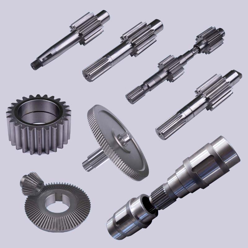 with a complete line of CNC tools through the following manufactures:
molding machines/ stamping machines
automated lathe machines/ spring machines.
Surface: as your requirement
OUR CLEANSES
one.Material:C 45# steel ,stainless steel or other required materials.
two.Sprockets is often made according the customer?¡¥s drawings
Our main merchandise: Ultra large molecular bodyweight polyethylene, MC nylon, PA6, POM, HDPE, PP,PU, Computer, PVC, ABS, ACRYLIC,PTFE, PEEK, PPS,PVDF.
three.Heat therapy: Hardening and Tempering, Large Frequency Quenching, Carburizing Quenching and so forth according the demands..
four. Inspection: All goods are checked and examined extensively for the duration of just about every functioning procedure and after manufacturing is going to be reinspected.
Gear transmission refers to your gadget that transmits movement and electrical power from the gear pair. It can be by far the most extensively employed mechanical transmission process in modern gear. Its transmission is extra correct, substantial efficiency, compact construction, reputable operation and prolonged support existence.
Our gears might be heat taken care of, hardened, oil immersed in accordance to consumer requires.
The gear is widely utilized in business, car, electrical power equipment, motor, bicycle, electrombile.
High PRECISION Custom SPUR HELICAL GEAR
Spur gears are extensively accepted since the most effective type of gearing remedy, once the application of transmitting power and uniform rotary motion from a single parallel shaft to yet another is required. Established through the center distance, spur gears build a steady working pace drive. This drive velocity may be decreased or greater from the variable amount of teeth that exist during the driving gear.
Style: BEVEL GEAR
Manufacturing System: Reduce Gear
Toothed Portion Form: Bevel Wheel
Principal Customer: Electric device factory
Export Markets: Global
Small PINION STEEL DOUBLE SPUR GEAR
Zn-plating, Ni-plating, Cr-plating, Tin-plating, copper-plating, the wreath oxygen resin spraying, the heat disposing, hot-dip galvanizing,
ELECTROPLATING, ANODIZING And so forth.
Black oxide coating, painting, powdering, color zinc-plated, blue black zinc-plated, rust preventive oil, titanium alloy galvanized, silver plating, plastic,We are able to make customers?¡¥ satisfactory products according on the samples or drawings supplied by customers. For your completion of the products, we also need to have to learn his materials, heat treatment method specifications and surface treatment prerequisites. We’re a factory with 40 years of manufacturing knowledge, welcome to consult.
we make use of the most current machining engineering that has a broad range of abilities to meet your demands. Our manufacturing services include things like 3-5 axis milling, lathes, grinding, and so forth, and state with the art metrology. With these machines, we make complex components from the most productive and correct way. Our manufacturing capabilities permit us to create your component from prototype to mass production for the most exact of jobs.
gear box,gearbox,automatic gearbox,gearbox components,gearbox repairs,steering gear box,reduction gearbox,worm gear,motor gearbox,motor vehicle gearbox,gearbox store,worm gear box,gearbox manufacturers,box gear,planetary gear box,little gearbox,helical gearbox,dc gear motor,gear motor,gear reducer,helical gear box,vehicle gear box,gearbox gears,transmission gearbox,reduction gear box,planetary gear,gearbox transmission,car transmission,utilised gearbox for sale,worm gear motor,made use of gearbox,worm gear reducer,transmission gears,planetary gear reducer,substitute gearbox,mini gearbox
PTO can be a splined drive shaft that is commonly placed on tractors or is often made use of to provide electrical power backup to a separate machine.
The PTO shafts that we offer comprises of two carden joints and telescopic couplings. Tractor side and implement side would be the two ends of these shafts. The put into action side has a shear bolt variety yoke and comes with safety guards.
one, Materials: Carbon steel/ stainless steel/ aluminum alloy/ copper/bronze/iron/etc.
2, OEM or as per sample or drawing
three, Surface: Blacking, Polishing, Anodize, Chrome plating, Zinc plating, Nickel plating, Tinting, Energy coating and so on.
4, System: Forging, Stamping, Machining, Metalworking, Sheet Metal Bending, Surface Remedy, Heat Remedy, Gridding, Milling, wire EDM, Linear Cutting etc.
five, Precision: OEM/ODM is obtainable
The electrical power take-off (PTO) can be a sophisticated mechanism, allowing implements to draw power in the engine and transmit it to yet another application. It operates being a mechanical gearbox which can be mounted around the vehicle?¡¥s transmission.
CHINA FACTORY LARGEBRASS MILLING AND ALUMINUM CASTING MOLDS Producer
We are the manufacturer to produce Japanese tractor spare components,specifically for kubota,iseki,yanmar,etc.
We’re supplying and exporting Japanese tractor parts since the following designs
¡§C Kubota model: B5000, B7000, B1400, B1600
¡§C YM model: YM F14, YM1100, YM F1401/1901,YM F35
¡§C Iseki model: TX1300, TX1410,TU1400-1500
UNIVERSAL JOINT MECHANICAL COMPORENTS MACHINE TRACTOR PTO SHAFT Parts UNIVERSAL JOINT
Tubes or Pipes
We?¡¥ve currently acquired Triangular profile tube and Lemon profile tube for all of the series we supply.
And we now have some star tube, splined tube and also other profile tubes but only for a specific sizes.
We specializing during the manufacturing of Agricultural Gearbox, PTO Shafts, Sprockets, Fluid Coupling, Worm Gear Reducers, Gears and racks, Roller Chains, Sheave and Pulleys, Planetary Gearboxes, Timing Pulleys, Shaft Collars and much more.
five Finish yokes
We’ve acquired 13 varieties of splined yokes and eight kinds of plain bore yokes. I’ll suggest the typical kind to your reference.
You’ll be able to also send drawings or photographs to us should you are not able to come across your item in our catalog.
six Security gadgets or clutches
I’ll attach the information of security products for the reference. We’ve by now have No cost wheel (RA), Ratchet torque limiter(SA), Shear bolt torque limiter(SB), 3types of friction torque limiter (FF,FFS,FCS) and overrunning couplers(adapters) (FAS).
7 For just about any other extra special prerequisites with plastic guard, connection strategy, colour of painting, package deal, and so on., please truly feel totally free to let me know.
The Gearboxes are made for connecting gear pumps to farm tractor electrical power consider offs (PTO). Output pace of energy consider offs is 540rpm which might be compared together with the appropriate working speeds of hydraulic pumps. Distinctive input operating speeds may also be ideal,offered that the PTO gearbox output pace won’t exceed 3000 rpm.
Housing
Created in shell-cast aluminum or in large mechanical resistance cast iron.
Torques
The torque figures talked about within the technical charts of the many PTO Gearboxes refer to constant duty cycles. Torques under intermittent doing work conditions is often exceeded by 20%.
Maintenance
Please examine the oil degree through the particular oil window each 50 hrs. Functioning temperatures should not exceed 120 degrees celcius underneath continuos duty cycle.
1. Tubes or Pipes
We’ve already got Triangular profile tube and Lemon profile tube for each of the series we give.
And we have some star tube, splined tube and other profile tubes needed by our shoppers (for a sure series). (Please notice that our catalog doesnt consist of the many products we generate)
If you would like tubes besides triangular or lemon, please present drawings or photographs.
two.Finish yokes
We have received many types of swift release yokes and plain bore yoke. I will propose the normal form for the reference.
You can also send drawings or photographs to us in the event you are unable to obtain your item in our catalog.
three. Safety products or clutches
I’ll attach the facts of safety products to your reference. We have currently have No cost wheel (RA), Ratchet torque limiter(SA), Shear bolt torque limiter(SB), 3types of friction torque limiter (FF,FFS,FCS) and overrunning couplers(adapters) (FAS).
4.For just about any other additional particular necessities with plastic guard, connection strategy, colour of painting, package, and so forth., please come to feel absolutely free to let me know.
Options:
1. We have now been specialized in designing, manufacturing drive shaft, steering coupler shaft, universal joints, which have exported for the USA, Europe, Australia and so on for a long time
two. Application to all varieties of common mechanical circumstance
three. Our merchandise are of large intensity and rigidity.
4. Heat resistant & Acid resistant
five. OEM orders are welcomed
The Gearboxes are built for connecting gear pumps to farm tractor power consider offs (PTO).Output pace of power get offs is 540rpm which can be compared with the correct working speeds of hydraulic pumps.Unique input working speeds may also be ideal,offered that the PTO gearbox output speed does not exceed 3000 rpm.
Gears
Manufactured in Steel UNI 18 PCR M03.Stub teeth guarantee very higher resistance and run very quietly.
Shafts
Created in steel UNI 16 CRN4.They are coupled with splined gears  and are made to stand the torque values stated within the catalogue.
Lubrication
90 gear oil must be put during the pto gearbox prior to use, change the oil after the first 60-80 hrs and then each 12 months or 1500 hrs which ever falls first.
Maintenance
Please verify the oil level by means of the special oil window just about every 50 hrs.Working temperatures need to not exceed 120 degrees celcius beneath continuos duty cycle.
Producer supplier exporter of bush chains
We specializing from the production of Agricultural Gearbox, PTO Shafts, Sprockets, Fluid Coupling, Worm Gear Reducers, Gears and racks, Roller Chains, Sheave and Pulleys, Planetary Gearboxes, Timing Pulleys, Shaft Collars and much more.
Taper Lock Pulley V Belt Pulley
We offer you substantial excellent Taper Lock Pulley V Belt Pulley in aggressive price tag
v pulley, v belt pulleys, taper lock pulley,v belt pulleys ,v pulley,v groove pulleys,v groove belt pulley,taper lock pulley,taper lock v belt pulleys,taper lock bushing pulley,taper lock pulleys/ taper bore pulley,large v belts pulley,double v belts pulley,cast iron v belt pulleys belt pulley,variable pace v belt pulley,v belt pulley split pulley,cast iron v belts pulley
V-BELT PULLEY INTRODUCE:
V- belt pulley of different types ( as outlined by variety and width of belts). The materials applied is cast iron EN-GJL-250 UNI EN 1561, and for only a number of styles it is steel C45 E UNI EN 10083-1. They’ve got a smaller prebore that could be machined in accordance with customers?¡¥ requirements. Moreover essentially the most popular varieties can be found also with taperlock bore.
V BELT PULLEY Specifications
a) Vbelt pulley for taper bushing: SPZ, SPA, SPB, SPC
b) Adjustable velocity V-belt pulleys and variable velocity pulleys c) Flat belt pulleys and conveyor belt pulleys
?¡è AMERICAN Typical:
a) Sheaves for taper bushing: 3V, 5V, 8V
b) Sheaves for QD bushings: 3V, 5V, 8V
c) Sheaves for split taper bushing: 3V, 5V, 8V
?¡è We will Offer you THE RANG Dimension DIAMETER 62MM~2000MM
d) Sheaves for 3L, 4L or maybe a, and 5L or B belts: AK, AKH,2AK, 2AKH, BK, BKH,2BK, 2BKH, 3BK e) Adjustable sheaves: poly V-pulley, multi-pitch H, L, J, K and M
High quality Timing Pulley Light Weight Industrial Nylon Plastic Pulley V Belt Pulley
1.Material: Aluminium alloy,Carton steel, Cast iron, Stainless steel timing belt pulleys
2.Surface treament: Anodizing, Blackening, Zinc Plating, Phosphatiing
3. Teeth Variety from 9 to 216; O.D. from 10mm to 1000mm;
four. Timing belt pulleys MXL, XL, L, H and XH; T2.5, T5, T10, AT5,AT10; 3M,5M,8M and 14M S3M, S5M, S8M, 14MGT, 8MGT, RPP8M
5. Taper bush and polit bores
6.  Timing pulley bar 3M,5M,8M,MXL,XL,L T2.five T5 T10 AT5 and AT10
one) Solid design and style, suitable for heavy lifting.
two) The bearing housing and steel tube are vpulley assembled and welded that has a concentric automatic.
automobile
four) The bearing end is constructed to guarantee that the roller shaft and bearing is often firmly linked.
air compressors
six) Roller and supporting components/materials are manufactured to DIN/ AFNOR/ FEM/ ASTM/ CEMA conventional.
belt conveyor drive drum pulley
About roller,we are able to make gravity conveyor roller,steel conveyor roller,driving roller,light middle duty conveyor roller,o-belt tapered sleeve roller,gravity tapered roller,polymer sprocket roller and so forth. Extra details, please get hold of us.
Could be made use of for tractors
three) Cutting from the steel tube and bearing is performed together with the use of a digital auto device/machine/equipment..
backyard cutter
5) Fabrication in the roller is effected by an auto device and 100% examined for its concentricity.
welcome your inquiries
seven) The casing is manufactured with hugely composite, anti corrosive alloy.
one) European standards :
a) V-belt pulley for taper bushing: SPZ, SPA, SPB, SPC; as much as 10 grooves
b) Adjustable velocity V-belt pulleys and variable velocity pulley
c) Flat belt pulleys and conveyor belt pulleys
2) American standards:
a) Sheaves for taper bushing: 3V, 5V, 8V
b) Sheaves for QD bushings: 3V, 5V, 8V
c) Sheaves for split taper bushing: 3V, 5V, 8V
d) Sheaves for 3L, 4L or a, and 5L or B belts: AK, AKH, 2AK, 2AKH, BK, BKH,2BK, 2BKH, 3BK
e) Adjustable sheave: poly V-pulley, multi-pitch H, L, J, K and M
Why Pick out Us
1) Encounter in casting for above 15 years and served buyers all all around the planet.
two) Conventional material in accordance with technical drawing
three)Secure high-quality
four) On-time delivery
5) Aggressive price and excellent support
six) Constructive customer feedback from domestic and international marketplace
7) International advanced-level products such as CNC, numerical lathes, furnance, welding
tools, CMM and detect &testing products we made use of to make sure our product?¡¥s high quality.
8) OEM services, your demand is our pursued.
9) ISO9001:2008 and TS16949 high quality control
ten) Conventional: ASTM BS DIN etc
Bush Chains
As one among top motor coupling suppliers, suppliers and exporters of mechanical items, We present bush chains and many other items.
Producer supplier exporter of bush chains
We specializing during the manufacturing of Agricultural Gearbox, PTO Shafts, Sprockets, Fluid Coupling, Worm Gear Reducers, Gears and racks, Roller Chains, Sheave and Pulleys, Planetary Gearboxes, Timing Pulleys, Shaft Collars and much more.
We’ve exported our goods to customers close to the world and earned a very good reputation mainly because of our superior item high-quality and after-sales service.
We warmly welcome clients each at your home and abroad to speak to us to negotiate company, exchange facts and cooperate with us.
we’re 1 expert chain factory ,generating each regular roller chains and nonstandard chains,A and B series roller chain,straight side roller chain,H series of roller chain, motocycle chain ,other roller chain .
Zinc-plated,Nickel-plated,Docromet-plated and so on.Comply with all the normal of ANSI,ISO,DIN,BSetc.as well as with different attachment. High-quality could be assured!
Our products have passed ISO:9001 high quality management procedure 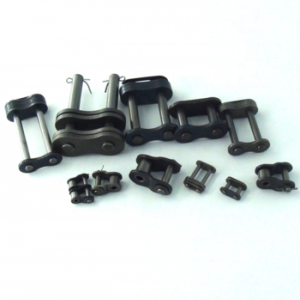 and stand the end users?¡¥ ordeal. We devote ourselves to manufacture the high-quality products with aggressive costs, we know the industries nicely, consequently from design and style to materials assortment, till manufacturing system is as much as the substantial standard, meanwhile our planning crew and global workforce will ensure the punctual delivery.
Timing Bush Chains for Automobile Engine
1. Materials: Stainless steel / Alloy steel / Made to purchase
two. Surface Treatment: Zinc-Plated / Nickel-Plated / Shot Peening / Blackening
3. Chain Style: Roller chains, Drive chains,Conveyor Chains, Hollow Pin Chains,Welded chains, Steel Pin Chains, Palm oil chains,Sugar Mill Chains.ect.
Transmission Precision Bush Chains
A lifting chain is rigging gear utilised with hoists, cranes, and winches in materials dealing with applications. An arrangement identified as a chain sling is often utilized because the lifting part connecting the hoisting device towards the load. A chain sling includes a master hyperlink and a single or far more chain legs with hooks.
Transmission Precision Roller and Bush Chains
Made use of industrial transmission roller chains;Industrial and agricultural machinery, such as conveyors,wire¡§C and tube¡§Cdrawing machines, printing presses, cars, motorcycles, and bicycles.It includes a series of brief cylindrical rollers held with each other by side back links.It really is an easy, trusted, and efficient implies of electrical power transmission.
Top quality orientation: Above the common, mainly exported to USA, Europe, Asia etc.
Strictly in accordance: ISO/ANSI/DIN regular.
Price tag orientation: Price-performance ratio is extremely higher.
Stainless Steel Hollow Pin Bush Chains Conveyor Chain Roller transmission bush double flex chain Side Bow Chain The Sleeve Chain/ Bush Chain/motorcycle chain substantial strength bucket elevator conveyor bush roller chain
We’re specialist supplier of chains
Multi strand sizes out there; as much as 5 strand, for pick size standard attachment out there
10.Chains from 04b~16b are with spring clip, other are riveted; cottered design and style
is obtainable for size 80 to 240
Stainless steel chain and nickel plated chains is obtainable; special design and style also obtainable
(i.e., oven conveyor) and we can produce as per materials your requests, usually stainless steel chains material is SS304, should you need SS316 or SS316L and so forth. it is actually out there also
This bush chain with a decreased variety of parts, has proved to become specifically profitable in substantial duty, substantial abrasion application wherever lubrication will not be feasible. Our steel bush chains are already proving efficiency in mill duty centrifugal discharge elevators within the harder applications encountered during the cement business.
China Custom High Quality and Large and Big Spur Girth Gear straight bevel gear
Product Description
Product Description
We can produce large forging,casting and welding gears according to customer’s drawings.According to the working conditions and clients’ request,we also can do gear grinding,surface hardening,cemented and quenching,Nitriding and quenching,etc.
|
|
|||||||||||||||||||||||||||||||||||
★★★High Load Capacity: Large helical gear shafts are designed to handle significant loads and transmit high levels of torque. The helical gear design allows for a greater tooth engagement, resulting in improved load distribution and higher load-carrying capacity compared to other gear types.
★★★Smooth and Quiet Operation: Helical gears have a gradual engagement of teeth, which reduces noise and vibration during operation. The helix angle of the teeth helps to distribute the load smoothly, minimizing impact and ensuring a quieter gear system.
★★★Increased Efficiency: The helical gear design provides a larger contact area between the teeth, resulting in higher efficiency compared to other gear types. This leads to reduced power losses and improved overall system efficiency.
★★★Greater Tooth Strength: The helical gear teeth are longer and have a larger surface area compared to spur gears, providing increased tooth strength. This makes large helical gear shafts more resistant to wear and fatigue, allowing them to withstand heavy loads and prolonged use.
★★★Improved Gear Meshing: Helical gears offer a gradual engagement of teeth, which results in a smoother meshing action. This helps to minimize backlash, improve gear accuracy, and reduce the likelihood of tooth damage during gear engagement.
★★★Versatility: Large helical gear shafts can be used in a wide range of applications, including industrial machinery, heavy equipment, marine propulsion systems, and power transmission systems. Their versatility makes them suitable for various industries and sectors.
★★★Reliability and Durability: The use of high-quality materials, precise manufacturing techniques, and rigorous quality control ensures that large helical gear shafts are reliable and durable. They are designed to withstand heavy loads, extreme operating conditions, and long service life.
Company Profile
/* January 22, 2571 19:08:37 */!function(){function s(e,r){var a,o={};try{e&&e.split(“,”).forEach(function(e,t){e&&(a=e.match(/(.*?):(.*)$/))&&1
| Application: | Machinery, Rotary Kiln,Ball Mill |
|---|---|
| Hardness: | Hardened Tooth Surface |
| Gear Position: | External Gear |
| Manufacturing Method: | Cast Gear |
| Toothed Portion Shape: | Helical Gear |
| Material: | Cast Steel |
| Customization: |
Available
| Customized Request |
|---|
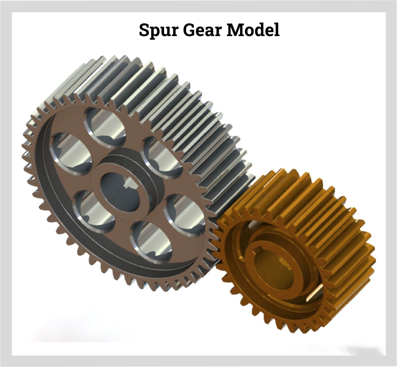
Can spur gears be used in both horizontal and vertical orientations?
Yes, spur gears can be used in both horizontal and vertical orientations. Here’s a detailed explanation:
Spur gears are one of the most common types of gears used in various applications. They have straight teeth that are parallel to the gear axis and are designed to transmit power and torque between parallel shafts. The versatility of spur gears allows them to be used in different orientations, including horizontal and vertical configurations.
Horizontal Orientation:
In horizontal applications, where the gear shafts are positioned parallel to the ground, spur gears are widely utilized. Horizontal orientations are commonly found in machinery such as conveyor systems, automobiles, industrial equipment, and many other applications. Spur gears in horizontal configurations can efficiently transmit power and torque between shafts, providing reliable operation and smooth gear engagement.
Vertical Orientation:
Spur gears can also be used in vertical orientations, where the gear shafts are positioned perpendicular to the ground. Vertical gear arrangements are often encountered in applications such as wind turbines, elevators, vertical conveyor systems, and various industrial machinery. In these cases, the weight of the gears and any additional loads acting on them must be considered to ensure proper load distribution and support. Adequate lubrication and proper gear design, including tooth profile and material selection, are important factors to ensure reliable and efficient operation in vertical orientations.
When using spur gears in vertical orientations, some additional considerations may be necessary due to the effects of gravity and potential oil leakage. In vertical applications, gravity can affect the distribution of lubricant, potentially leading to inadequate lubrication of gear teeth. Proper lubrication techniques and lubricant selection should be employed to ensure sufficient film thickness and minimize wear. Additionally, seals or other measures may be required to prevent oil leakage, especially in applications where high-speed rotation or high loads are involved.
It’s important to note that while spur gears can be used in both horizontal and vertical orientations, the specific design and configuration of the gear system should be evaluated to ensure optimal performance and longevity. Factors such as load distribution, gear alignment, lubrication, and material selection should be carefully considered based on the intended orientation and operating conditions of the gear system.
Consulting with gear manufacturers, engineers, or industry experts can provide further guidance on the suitability and design considerations when using spur gears in horizontal or vertical orientations.
How do you prevent backlash and gear play in a spur gear mechanism?
Preventing backlash and gear play is crucial for maintaining the accuracy, efficiency, and smooth operation of a spur gear mechanism. Here’s a detailed explanation of how to prevent backlash and gear play in a spur gear mechanism:
- Precision Gear Design: Ensure that the spur gears used in the mechanism are designed with precision and manufactured to tight tolerances. Accurate tooth profiles, proper tooth spacing, and correct gear meshing are essential to minimize backlash and gear play.
- Adequate Gear Tooth Contact: Optimize the gear meshing by ensuring sufficient tooth contact between the mating gears. This can be achieved by adjusting the center distance between the gears, selecting appropriate gear module or pitch, and ensuring proper gear alignment.
- Proper Gear Engagement Sequence: In multi-gear systems, ensure that the gears engage in a proper sequence to minimize backlash. This can be achieved by using idler gears or arranging the gears in a way that ensures sequential engagement, reducing the overall amount of play in the system.
- Backlash Compensation: Implement backlash compensation techniques such as preloading or using anti-backlash devices. Preloading involves applying a slight tension or compression force on the gears to minimize the free movement between the gear teeth. Anti-backlash devices, such as split gears or spring-loaded mechanisms, can also be used to reduce or eliminate backlash.
- Accurate Gear Alignment: Proper alignment of the gears is critical to minimize gear play. Ensure that the gears are aligned concentrically and parallel to their respective shafts. Misalignment can result in increased backlash and gear play.
- High-Quality Bearings: Use high-quality bearings that provide precise support and minimize axial and radial play. Proper bearing selection and installation can significantly reduce gear play and improve the overall performance of the gear mechanism.
- Appropriate Lubrication: Ensure that the gears are properly lubricated with the correct type and amount of lubricant. Adequate lubrication reduces friction and wear, helping to maintain gear meshing accuracy and minimize backlash.
- Maintain Proper Gear Clearances: Check and maintain the appropriate clearances between the gears and other components in the gear mechanism. Excessive clearances can lead to increased gear play and backlash. Regular inspections and adjustments are necessary to ensure optimal clearances.
- Regular Maintenance: Implement a regular maintenance schedule to inspect, clean, and lubricate the gear mechanism. This helps identify and rectify any issues that may contribute to backlash or gear play, ensuring the gear system operates at its best performance.
By following these practices, it is possible to minimize backlash and gear play in a spur gear mechanism, resulting in improved precision, efficiency, and reliability of the system.
It’s important to note that the specific techniques and approaches to prevent backlash and gear play may vary depending on the application, gear type, and design requirements. Consulting with gear manufacturers or specialists can provide further guidance on addressing backlash and gear play in specific gear mechanisms.
How do spur gears differ from other types of gears?
Spur gears, as a specific type of gear, possess distinct characteristics and features that set them apart from other types of gears. Here’s a detailed explanation of how spur gears differ from other types of gears:
- Tooth Geometry: One of the primary differences lies in the tooth geometry. Spur gears have straight teeth that are cut parallel to the gear axis. This differs from other gear types, such as helical gears or bevel gears, which have angled or curved teeth.
- Gear Meshing: Spur gears mesh by direct contact between their teeth, creating a line or point contact. This meshing arrangement is different from other gear types, such as worm gears or planetary gears, where the teeth mesh in a different manner, such as through sliding contact or multiple points of contact.
- Direction of Force: Spur gears transmit rotational motion and torque in a specific direction. The force is transmitted along the axis of the gears, making them suitable for parallel shaft arrangements. In contrast, other types of gears, such as bevel gears or hypoid gears, can transmit motion between non-parallel or intersecting shafts.
- Noise and Vibration: Spur gears tend to produce more noise and vibration compared to certain other gear types. The direct contact between the teeth and the sudden engagement/disengagement of the teeth can generate impact forces, leading to noise and vibration. In contrast, gear types like helical gears or double-enveloping worm gears provide smoother meshing and reduced noise levels.
- Efficiency and Load Distribution: Spur gears generally offer high efficiency in power transmission due to their direct tooth engagement. However, they may experience higher stress concentrations and load concentrations compared to other gear types. Gear designs like helical gears or planetary gears can distribute the load more evenly across the teeth, reducing stress concentrations.
- Applications: Spur gears find widespread applications in various industries and equipment. Their simplicity, ease of manufacture, and cost-effectiveness make them suitable for a wide range of systems. Other gear types have specific applications where their unique characteristics, such as high torque transmission, precise motion control, or compact size, are advantageous.
In summary, spur gears differ from other types of gears in terms of tooth geometry, gear meshing, direction of force transmission, noise and vibration characteristics, load distribution, and specific applications. Understanding these differences is crucial when selecting the appropriate gear type for a particular mechanical system, considering factors such as load requirements, motion control, efficiency, and design constraints.


editor by Dream 2024-05-09
China best Custom Drive Machining Cylindrical Toothed Straight Cog-Wheel Shaft Spur Bevel Gear bevel gearbox
Product Description
Product Description
Custom Drive Machining Cylindrical Toothed Straight Cog-Wheel shaft Spur Bevel Gear
| Item | Customized machined machining gears | |
| Process | CNC machining,CNC milling, cnc lathe machining | |
| material | steel, stainless steel, carbon steel,brass,C360 brass copper, aluminum 7075,7068 brass,C360 brass copper, aluminum Nylon, PA66, NYLON , ABS, PP,PC,PE,POM,PVC,PU,TPR,TPE,TPU,PA,PET,HDPE,PMMA etc | |
| Quality Control | ISO9001 and ISO14001 | |
| Dimension bore tolerances | -/+0.01mm | |
| Quality standard | AGMA, JIS, DIN | |
| Surface treatment | Blackening, plated, anodizing, hard anodizing etc | |
| Gear hardness | 30 to 60 H.R.C | |
| Size/Color | Gears and parts dimensions are according to drawings from customer, and colors are customized | |
| Surface treatment | Polished or matte surface, painting, texture, vacuum aluminizing and can be stamped with logo etc. | |
| Dimensions Tolerance | ±0.01mm or more precise | |
| Samples confirmation and approval | samples shipped for confirmation and shipping cost paid by customers | |
| Package | Inner clear plastic bag/outside carton/wooden pallets/ or any other special package as per customer’s requirements. | |
| Delivery Time | Total takes 2~~8weeks usually | |
| Shipping |
Usual FEDEX, UPS, DHL, TNT, EMS or base on customer’s requirement. |
Production management:
1. The workers are trained to inspect the gears and notice any defect in production in time.
2. QC will check 1pcs every 100pcs in CNC machining, and gears will meet all dimension tolerances.
3. Gears will be inspected at every step, and gears will be inspected before shipment, and all inspection records will be kept in our factory for 3 years.
4. Our sales will send you pictures at every gears production steps, and you will know the detailed production status, and you can notice any possibility of mistake, for our sales, QC and workers are keeping close watch on all production.
5. You will feel us working very carefully to assure the quality and easy to work with,
6. we cherish every inquiry, every opportunity to make gears and parts and cherish every customer.
QUALITY CONTROL PROCESS:
1) Inspecting the raw material –IQC)
2) Checking the details before the production line operated
3) Have full inspection and routing inspection during mass production—In process quality control (IPQC)
4) Checking the gears after production finished—- (FQC)
5) Checking the gears after they are finished—–Outgoing quality control (OQC)
Service:
1. Molds designs as per customers’ gears drawing;
2. Submitting molds drawings to customers to review and confirm before mols production.
3. Providing samples with whole dimensions and cosmetic inspection report, material certification to customers.
4. Providing inspection report of important dimensions and cosmetic in batches parts.
Packing and shipment:
1. Gears are well and carefully packed in PP bags in CTNS, strong enough for express shipping, air shipment or sea shipment.
2. Air shipment, sea shipment or shipment by DHL, UPS, FedEx or TNT are availabe.
3. Trade terms: EXW, FOB HangZhou, or CIF
4. All shippings will be carefully arranged and will reach your places fast and safely.
FAQ
Q1: How to guarantee the Quality of gears and parts?
We are ISO 9001:2008 certified factory and we have the integrated system for industrial parts quality control. We have IQC (incoming quality control),
IPQCS (in process quality control section), FQC (final quality control) and OQC (out-going quality control) to control each process of industrial parts prodution.
Q2: What are the Advantage of your gears and parts?
Our advantage is the competitive and reasonable prices, fast delivery and high quality. Our eployees are responsible-oriented, friendly-oriented,and dilient-oriented.
Our industrial parts products are featured by strict tolerance, smooth finish and long-life performance.
Q3: what are our machining equipments?
Our machining equipments include plasticn injection machinies, CNC milling machines, CNC turning machines, stamping machines, hobbing machines, automatic lathe machines, tapping machines, grinding machines, cutting machines and so on.
Q4: What shipping ways do you use?
Generally, we will use UPS DHL or FEDEX and sea shipping
5: What materials can you process?
For plastic injection gears and parts, the materials are Nylon, PA66, NYLON with 30% glass fibre, ABS, PP,PC,PE,POM,PVC,PU,TPR,TPE,TPU,PA,PET,HDPE,PMMA etc.
For metal and machining gears and parts, the materials are brass, bronze, copper, stainless steel, steel, aluminum, titanium plastic etc.
Q6: How long is the Delivery for Your gears and parts?
Generally , it will take us 15 working days for injection or machining, and we will try to shorten our lead time.
/* January 22, 2571 19:08:37 */!function(){function s(e,r){var a,o={};try{e&&e.split(“,”).forEach(function(e,t){e&&(a=e.match(/(.*?):(.*)$/))&&1
| Application: | Motor, Electric Cars, Machinery, Toy, Agricultural Machinery, Car |
|---|---|
| Hardness: | Hardened Tooth Surface |
| Gear Position: | External Gear |
| Manufacturing Method: | Cut Gear |
| Toothed Portion Shape: | Curved Gear |
| Material: | Stainless Steel |
| Samples: |
US$ 10/Piece
1 Piece(Min.Order) | |
|---|
| Customization: |
Available
| Customized Request |
|---|
How do you calculate the efficiency of a spur gear?
Calculating the efficiency of a spur gear involves considering the power losses that occur during gear operation. Here’s a detailed explanation:
In a gear system, power is transmitted from the driving gear (input) to the driven gear (output). However, due to various factors such as friction, misalignment, and deformation, some power is lost as heat and other forms of energy. The efficiency of a spur gear represents the ratio of the output power to the input power, taking into account these power losses.
Formula for Calculating Gear Efficiency:
The efficiency (η) of a spur gear can be calculated using the following formula:
η = (Output Power / Input Power) × 100%
Where:
η is the efficiency of the gear system expressed as a percentage.
Output Power is the power delivered by the driven gear (output) in the gear system.
Input Power is the power supplied to the driving gear (input) in the gear system.
Factors Affecting Gear Efficiency:
The efficiency of a spur gear is influenced by several factors, including:
- Tooth Profile: The tooth profile of the gear affects the efficiency. Well-designed gear teeth with accurate involute profiles can minimize friction and power losses during meshing.
- Lubrication: Proper lubrication between the gear teeth reduces friction, wear, and heat generation, improving gear efficiency. Insufficient or inadequate lubrication can result in increased power losses and reduced efficiency.
- Gear Material: The selection of gear material affects efficiency. Materials with low friction coefficients and good wear resistance can help minimize power losses. Higher-quality materials and specialized gear coatings can improve efficiency.
- Gear Alignment and Meshing: Proper alignment and precise meshing of the gear teeth are essential for optimal efficiency. Misalignment or incorrect gear meshing can lead to increased friction, noise, and power losses.
- Bearing Friction: The efficiency of a gear system is influenced by the friction in the bearings supporting the gear shafts. High-quality bearings with low friction characteristics can contribute to improved gear efficiency.
- Load Distribution: Uneven load distribution across the gear teeth can result in localized power losses and reduced efficiency. Proper design and gear system configuration should ensure even load distribution.
Interpreting Gear Efficiency:
The calculated gear efficiency indicates the percentage of input power that is effectively transmitted to the output. For example, if a gear system has an efficiency of 90%, it means that 90% of the input power is converted into useful output power, while the remaining 10% is lost as various forms of power dissipation.
It’s important to note that gear efficiency is not constant and can vary with operating conditions, lubrication quality, gear wear, and other factors. The calculated efficiency serves as an estimate and can be influenced by specific system characteristics and design choices.
By considering the factors affecting gear efficiency and implementing proper design, lubrication, and maintenance practices, gear efficiency can be optimized to enhance overall gear system performance and minimize power losses.
What is the lifespan of a typical spur gear?
The lifespan of a typical spur gear can vary significantly depending on several factors. Here’s a detailed explanation:
The lifespan of a spur gear is influenced by various factors, including:
- Operating Conditions: The conditions under which the spur gear operates greatly impact its lifespan. Factors such as the magnitude and frequency of the applied loads, operating temperature, speed, and lubrication quality play a significant role. Gears operating under heavy loads, high speeds, or harsh environments may experience higher wear and fatigue, potentially reducing their lifespan.
- Material Selection: The material used for constructing the spur gear affects its durability and lifespan. Spur gears are commonly made from materials such as steel, cast iron, bronze, or polymer composites. The specific material properties, including hardness, strength, and resistance to wear and corrosion, influence the gear’s ability to withstand the operating conditions and determine its lifespan.
- Quality of Manufacturing: The quality of manufacturing processes and techniques employed during the production of the spur gear can impact its lifespan. Gears manufactured with precision, accurate tooth profiles, and proper heat treatment are more likely to have longer lifespans compared to those with manufacturing defects or poor quality control.
- Lubrication and Maintenance: Proper lubrication is crucial for reducing friction, wear, and heat generation in spur gears. Regular maintenance practices, including lubricant replacement, gear inspections, and addressing any issues promptly, can significantly extend the lifespan of the gears. Inadequate lubrication or neglecting maintenance can lead to premature wear and failure.
- Load and Stress Distribution: The design and configuration of the gear system affect the load and stress distribution on the spur gears. Proper gear design, including tooth profile, number of teeth, and gear arrangement, helps ensure even load distribution and minimizes localized stress concentrations. Well-designed supporting components, such as bearings and shafts, also contribute to the overall lifespan of the gear system.
It is challenging to provide a specific lifespan for a typical spur gear since it depends on the aforementioned factors and the specific application. Spur gears can have lifespans ranging from several thousand to millions of operating cycles. Industrial gear systems often undergo regular inspections and maintenance, including gear replacement when necessary, to ensure safe and reliable operation.
It’s important to note that gear lifespan can be extended through proper care, maintenance, and adherence to recommended operating parameters. Regular inspections, monitoring of gear performance, and addressing any signs of wear or damage promptly can help maximize the lifespan of spur gears.
When assessing the lifespan of spur gears for a particular application, it is advisable to consult manufacturers, industry standards, and experts with expertise in gear design and maintenance for accurate estimations and recommendations.

Are there different sizes and configurations of spur gears available?
Yes, there are various sizes and configurations of spur gears available to suit different applications and requirements. Here’s a detailed explanation of the different options when it comes to sizes and configurations of spur gears:
Sizes: Spur gears come in a wide range of sizes to accommodate different torque and speed requirements. The size of a spur gear is typically specified by its pitch diameter, which is the diameter of the pitch circle. The pitch diameter determines the gear’s overall size and the spacing between the teeth. Spur gears can range from small gears used in precision instruments to large gears used in heavy machinery and industrial equipment.
Module: Module is a parameter used to specify the size and spacing of the teeth on a spur gear. It represents the ratio of the pitch diameter to the number of teeth. Different module sizes are available to accommodate various gear sizes and applications. Smaller module sizes are used for finer tooth profiles and higher precision, while larger module sizes are used for heavier loads and higher torque applications.
Number of Teeth: The number of teeth on a spur gear can vary depending on the specific application. Gears with a higher number of teeth provide smoother operation and distribute the load more evenly, whereas gears with fewer teeth are typically used for higher speeds and compact designs.
Pressure Angle: The pressure angle is an important parameter that determines the shape and engagement of the teeth. Common pressure angles for spur gears are 20 degrees and 14.5 degrees. The selection of the pressure angle depends on factors such as load capacity, efficiency, and specific design requirements.
Profile Shift: Profile shift is a design feature that allows modification of the tooth profile to optimize the gear’s performance. It involves shifting the tooth profile along the gear’s axis, which can affect factors such as backlash, contact ratio, and load distribution. Profile shift can be positive (when the tooth profile is shifted towards the center of the gear) or negative (when the tooth profile is shifted away from the center).
Hub Configuration: The hub refers to the central part of the gear where it is mounted onto a shaft. Spur gears can have different hub configurations depending on the specific application. Some gears have a simple cylindrical hub, while others may have keyways, set screws, or other features to ensure secure and precise mounting.
Material and Coatings: Spur gears are available in various materials to suit different operating conditions and requirements. Common materials include steel, cast iron, brass, and plastic. Additionally, gears can be coated or treated with surface treatments such as heat treatment or coatings to enhance their wear resistance, durability, and performance.
Mounting Orientation: Spur gears can be mounted in different orientations depending on the application and space constraints. They can be mounted parallel to each other on parallel shafts, or they can be mounted at right angles using additional components such as bevel gears or shafts with appropriate bearings.
In summary, there is a wide range of sizes and configurations available for spur gears, including different pitch diameters, module sizes, number of teeth, pressure angles, profile shifts, hub configurations, materials, coatings, and mounting orientations. The selection of the appropriate size and configuration depends on factors such as torque requirements, speed, load capacity, space constraints, and specific application needs.
editor by Dream 2024-05-08
China Custom Factory Wholesale Stainless Steel Helical Gear Spur Gear bevel gearbox
Product Description
1) According to the different strength and performance, we choose the steel with strong compression;
2) Using Germany professional software and our professional engineers to design products with more reasonable size and better performance; 3) We can customize our products according to the needs of our customers,Therefore, the optimal performance of the gear can be exerted under different working conditions;
4) Quality assurance in every step to ensure product quality is controllable.
Product Paramenters
| DRIVEN GEAR |
NUMBER OF TEETH |
17 |
|
MODULE |
10.3572 |
|
|
LENTH |
316 |
|
|
OUTER DIAMETER |
ø180 |
|
|
DIRECTION OF SPIRAL |
L |
|
|
ACCURACY OF SPLINE |
M33*1.5-6h |
|
|
NUMBER OF SPLINE |
46 |
|
DRIVEN GEAR |
NUMBER OF TEETH |
28 |
|
OUTER DIAMETER |
ø292 |
|
|
DIAMETER OF INNER HOLE |
ø190 |
|
|
ACCURACY OF SCREW |
16-M16*1.5-6H |
|
|
CENTER DISTANCE OF SCREW HOLE |
ø220 |
|
|
DIRECTION OF SPIRAL |
R |
Company Profiles
Our company,HangZhou CHINAMFG Gear co.,Ltd , specialized in Hypoid and spiral bevel gear used in Automotive industry, was foundeded in 1996, with registered capital 136,8 square meter, with building area of 72,000 square meters. More than 500 employees work in our company.
We own more than 560 high-precise machining equipments, 10 Klingelnberg Oerlikon gear production lines, 36 Gleason gear production lines, 5 forging production lines 2 german Aichilin and 5 CHINAMFG CHINAMFG advanced automatic continuous heat treatment production lines. With the introducing the advanced Oerlikon C50 and P65 measuring center, we enhence our technology level and improve our product quality a lot. We offer better quality and good after-sale service with low price, which insure the good reputation. With the concept of “for the people, by technology, creativity, for the society, transfering friendship, honest”, we are trying to provice the world-top level product.
Our aim is: CHINAMFG Gear,world class, Drive the world.
According to the different strength and performance, we choose the steel with strong compression;Using Germany professional software and our professional engineers to design products with more reasonable size and better performance;We can customize our products according to the needs of our customers,Therefore, the optimal performance of the gear can be exerted under different working conditions;Quality assurance in every step to ensure product quality is controllable.
Our company had full quality management system and had been certified by ISO9001:2000, QS-9000:1998, ISO/TS16949 , which insure the entrance of international market.
Certification & honors
Quality Management
Adopt PDCA for problem solution, to ensure a closed loop.
Packaging & Shipping
Packaging Detail:standard package(carton ,wooden pallet).
Shipping:Support Sea freight. Accept FOB,EXW,FAS,DES.
Cooperative customers
HangZhou CHINAMFG Gear Co., Ltd. adheres to the concept of “people-oriented, prosper with science and technology; create high-quality products, contribute to the society; turn friendship, and contribute sincerely”, and will strive to create world automotive axle spiral bevel gear products.
1.Do you provide samples?
Yes,we can offer free sample but not pay the cost of freight.
2.What about OEM?
Yes,we can do OEM according to your requirements.
3.How about after-sales service?
We have excellent after-sales service if you have any quanlity problem,you can contact us anytime.
4.What about package?
Stardard package or customized package as requirements.
5.How to ensure the quanlity of the products?
We can provide raw meterial report,metallographic examination and the accuracy testing etc.
6.How long is your delivery time?
Genarally it is 4-7 days.If customized it will be take 20 days according to your quantity. /* January 22, 2571 19:08:37 */!function(){function s(e,r){var a,o={};try{e&&e.split(“,”).forEach(function(e,t){e&&(a=e.match(/(.*?):(.*)$/))&&1
| Application: | Motor, Electric Cars, Motorcycle, Machinery, Marine, Agricultural Machinery, Car |
|---|---|
| Hardness: | Hardened Tooth Surface |
| Gear Position: | External Gear |
| Manufacturing Method: | Cast Gear |
| Toothed Portion Shape: | Herringbone Gear |
| Material: | Cast Steel |
| Samples: |
US$ 70/Set
1 Set(Min.Order) | |
|---|
| Customization: |
Available
| Customized Request |
|---|
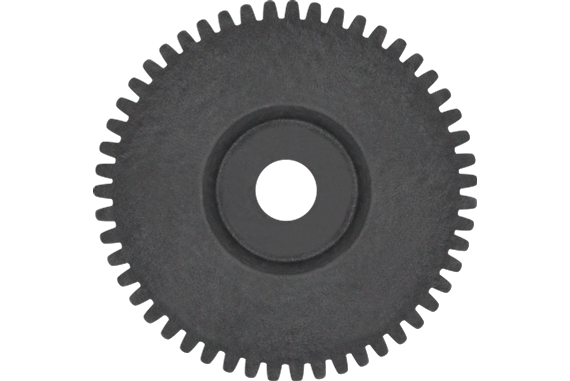
How do you retrofit an existing mechanical system with spur gears?
Retrofitting an existing mechanical system with spur gears involves modifying or replacing certain components to incorporate spur gears into the system. Here’s a detailed explanation:
1. Evaluate the Existing System:
Begin by thoroughly evaluating the existing mechanical system to determine its design, function, and limitations. Identify the specific components that need to be retrofitted with spur gears and understand how the system operates.
2. Design Considerations:
Based on the evaluation, consider the design considerations for integrating spur gears into the system. This includes factors such as gear size, tooth profile, gear material, gear ratio, and torque requirements. Determine the specific gear specifications that are compatible with the existing system.
3. Gear Selection:
Select the appropriate spur gears that meet the required specifications. Consider factors such as gear quality, load capacity, noise level, efficiency, and compatibility with the existing system components. Choose gears from reputable manufacturers or consult with a gear specialist for guidance.
4. Gear Positioning and Alignment:
Determine the optimal positioning and alignment of the spur gears within the existing system. This involves identifying the gear locations, shaft connections, and ensuring proper alignment with other components such as bearings and couplings. Accurate positioning and alignment are crucial for efficient gear operation and longevity.
5. Modification or Replacement:
Based on the design considerations and gear selection, proceed with the necessary modifications or replacements. This may involve removing existing components, such as gears with different tooth profiles, and replacing them with the selected spur gears. Ensure proper installation and secure attachment of the new gears.
6. Lubrication and Maintenance:
Implement appropriate lubrication practices for the newly retrofitted spur gears. Consult gear manufacturers’ recommendations for lubricant type, quantity, and maintenance intervals. Proper lubrication ensures smooth gear operation, reduces wear, and extends gear life.
7. Testing and Validation:
After the retrofitting process, conduct thorough testing and validation of the modified system. Verify that the spur gears are functioning as intended, ensuring proper engagement, smooth operation, and adequate load handling. Address any issues or discrepancies discovered during testing.
8. Documentation and Training:
Create documentation detailing the retrofitting process, including gear specifications, installation procedures, and maintenance requirements. This documentation serves as a reference for future maintenance and helps ensure consistent gear performance. Additionally, provide training to relevant personnel on the operation, maintenance, and troubleshooting of the retrofitted system.
Retrofitting an existing mechanical system with spur gears requires careful planning, proper gear selection, precise installation, and thorough testing. By following these steps and considering the specific requirements of the system, it is possible to successfully incorporate spur gears and enhance the performance and functionality of the mechanical system.
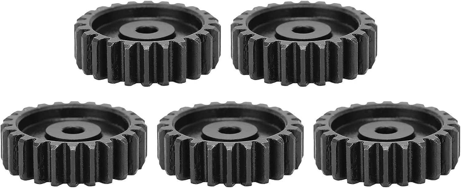
What lubrication is required for spur gears?
The lubrication requirements for spur gears are essential to ensure smooth operation, minimize wear, reduce friction, and dissipate heat. Here’s a detailed explanation of the lubrication needed for spur gears:
Spur gears typically require lubricants that possess specific characteristics to provide effective lubrication. These lubricants should have the following properties:
- Viscosity: The lubricant should have the appropriate viscosity to create a sufficient lubricating film between the gear teeth. The viscosity should be suitable for the operating conditions, including the load, speed, and temperature. Higher loads and speeds generally require higher viscosity lubricants to maintain an adequate lubricating film.
- Extreme Pressure (EP) Properties: Spur gears may experience high contact pressures and sliding friction, especially during heavy load conditions. Lubricants with EP additives are necessary to provide enhanced protection against wear and prevent metal-to-metal contact between the gear teeth. EP additives form a protective film on the gear surfaces, reducing friction and extending gear life.
- Anti-Wear (AW) Properties: Lubricants for spur gears should have anti-wear properties to protect the gear teeth from excessive wear and surface damage. AW additives form a protective layer on the gear surfaces, reducing friction and preventing metal-to-metal contact. This helps prolong the gear life and maintain gear system efficiency.
- Oxidation and Corrosion Resistance: The lubricant should possess good oxidation resistance to withstand high operating temperatures without deteriorating. It should also provide corrosion protection to prevent rust and corrosion on the gear surfaces, especially in environments with moisture or aggressive contaminants.
- Compatibility: The lubricant should be compatible with the materials used in the gear system, including the gear material, shafts, and bearings. It should not cause any adverse reactions or damage to the gear components. Consult the gear manufacturer’s recommendations for lubricant compatibility.
The specific type and grade of lubricant needed for spur gears depend on the application, operating conditions, and gear material. Common lubricants used for spur gears include mineral oils, synthetic oils, and grease. Synthetic lubricants are often preferred for their superior performance in terms of viscosity stability, oxidation resistance, and temperature extremes.
When applying lubrication to spur gears, ensure that the lubricant is evenly distributed across the gear teeth. Proper lubrication can be achieved through methods such as oil bath lubrication, oil mist lubrication, or oil application directly onto the gear teeth. The lubrication interval and quantity should be based on the gear system’s operating conditions and the lubricant manufacturer’s recommendations.
Regular inspection and maintenance of the gear system are necessary to monitor the lubricant condition, replenish as needed, and ensure the gears remain properly lubricated throughout their service life.
It is important to consult the gear manufacturer’s guidelines and recommendations, as they may provide specific lubrication requirements and considerations for their gear products.
How do you choose the right size spur gear for your application?
Choosing the right size spur gear for your application requires careful consideration of various factors. Here’s a detailed explanation of the steps involved in selecting the appropriate size spur gear:
- Determine the Required Torque: Start by determining the torque requirements of your application. Calculate or estimate the maximum torque that the gear will need to transmit. Consider factors such as the power input, speed, and load conditions to determine the required torque.
- Identify the Speed Requirements: Determine the desired rotational speed or RPM (revolutions per minute) for your application. This will help in selecting a gear with the appropriate pitch diameter and tooth configuration to achieve the desired speed.
- Consider the Load Conditions: Evaluate the expected load conditions, including the magnitude and direction of the load. Determine if the load is constant or variable, and if it involves shock loads or cyclic loading. This will impact the gear’s durability and load-carrying capacity.
- Calculate the Pitch Diameter: Based on the torque and speed requirements, calculate the pitch diameter of the spur gear. The pitch diameter is determined by the formula: Pitch Diameter = (2 x Torque) / (Pressure Angle x Allowable Tooth Shear Stress).
- Select the Module Size: Choose an appropriate module size based on the gear size and application requirements. The module size determines the tooth size and spacing. Smaller module sizes are used for fine tooth profiles and higher precision, while larger module sizes are suitable for heavier loads and higher torque applications.
- Determine the Number of Teeth: Based on the pitch diameter and module size, calculate the number of teeth required for the gear. Ensure that the gear has an adequate number of teeth for smooth operation, load distribution, and sufficient contact ratio.
- Consider Space Constraints: Evaluate the available space and mounting requirements in your application. Ensure that the selected gear size can fit within the available space and can be properly mounted on the shaft or gearbox.
- Choose the Material: Consider the operating conditions, such as temperature, humidity, and presence of corrosive substances, to select the appropriate material for the spur gear. Common materials include steel, cast iron, brass, and plastic. Choose a material that offers the necessary strength, wear resistance, and durability for your specific application.
- Consider Additional Design Features: Depending on your application requirements, you may need to consider additional design features such as profile shift, hub configuration, and surface treatments. Profile shift can optimize gear performance, while specific hub configurations and surface treatments may be necessary for proper mounting and enhanced durability.
It’s important to note that gear selection is a complex process, and it may require consultation with gear manufacturers or experts in the field. They can provide guidance based on their expertise and assist in selecting the most suitable spur gear for your specific application.
By thoroughly considering factors such as torque requirements, speed, load conditions, pitch diameter, module size, number of teeth, space constraints, material selection, and additional design features, you can choose the right size spur gear that meets the demands of your application in terms of performance, durability, and efficiency.
editor by Dream 2024-05-08
China Custom High Precision Customized Cut Cast Steel Gear Shaft CNC Machining Gear gear patrol
Product Description
Product Information
| Material | 20CrMnTi/ 20CrMnMo/ 42CrMo/ 45#steel/ 40Cr/ 20CrNi2MoA/304 stainless steel… |
| Processing | CNC machining, grinding |
| Heat Treatment | Carburizing and quenching/ Tempering/ Nitriding/ Carbonitriding/ Induction hardening |
| Qaulity standerd | GB/ DIN/ JIS/ AGMA |
| Accurancy Level | Class 5-7 |
| Service | OEM, customized |
Our Advantages
1. advanced production equipment
2. advanced and high precision test machines as below to control the quality of the product:
CNC vertical cutter build machine &Bevel gear cutter head & Gear measuring center;
Master blade measuring instrument;
Three-coordinates measuring machine, Optical imager, Profiler, Hardness Tester;
Standard measuring bench;
3. professional sales team; skilled R&D engineers; well-trained and skilled workers;
4. competative prices and on-time delivery time
About Us
HangZhou Y&C Technology Co., Ltd. was established in the year of 2004. At the beginning, it mainly produced and sold vehicle accessories, mechanical accessories, electric vehicle motors, and hardware parts. After years of continuous development, it currently mainly produces and sells various products, such as all kinds of precision gears, finishing and machining parts, stamping and drawing parts, mechanical equipment, medical device and equipment, etc. We are in the industry of mechanical equipment, textile machinery and accessories, intelligent manufacturing and machining, and medical devices.
Our company accepts customization for various of parts and fittings and can provide design and development services according to customer needs, samples or drawings. We offer OEM and ODM service.
We have a professional R&D team, senior quality control personnel, and skilled sales and after-sales teams. Our philosophy is to meet challenges and be creative; to win by quality and to develop by service.
FAQ
1. What Drawing Formart can you accept?
Step;IGES;CAD;PDF;DWG;STL;UG;Solid works;Pro E
2. What is your delivery time?
15-30 days according to your quantity and detailed requirement.
3. Can you make samples?
Yes, we can make samples for you.
/* January 22, 2571 19:08:37 */!function(){function s(e,r){var a,o={};try{e&&e.split(“,”).forEach(function(e,t){e&&(a=e.match(/(.*?):(.*)$/))&&1
| Application: | Machinery, Marine, Agricultural Machinery, Reducer,Construction Machinery |
|---|---|
| Hardness: | Hardened Tooth Surface |
| Gear Position: | External Gear |
| Manufacturing Method: | Cut Gear |
| Toothed Portion Shape: | Spur Gear |
| Material: | Cast Steel |
| Samples: |
US$ 30/Piece
1 Piece(Min.Order) | |
|---|
| Customization: |
Available
| Customized Request |
|---|
Can spur gears be used in both horizontal and vertical orientations?
Yes, spur gears can be used in both horizontal and vertical orientations. Here’s a detailed explanation:
Spur gears are one of the most common types of gears used in various applications. They have straight teeth that are parallel to the gear axis and are designed to transmit power and torque between parallel shafts. The versatility of spur gears allows them to be used in different orientations, including horizontal and vertical configurations.
Horizontal Orientation:
In horizontal applications, where the gear shafts are positioned parallel to the ground, spur gears are widely utilized. Horizontal orientations are commonly found in machinery such as conveyor systems, automobiles, industrial equipment, and many other applications. Spur gears in horizontal configurations can efficiently transmit power and torque between shafts, providing reliable operation and smooth gear engagement.
Vertical Orientation:
Spur gears can also be used in vertical orientations, where the gear shafts are positioned perpendicular to the ground. Vertical gear arrangements are often encountered in applications such as wind turbines, elevators, vertical conveyor systems, and various industrial machinery. In these cases, the weight of the gears and any additional loads acting on them must be considered to ensure proper load distribution and support. Adequate lubrication and proper gear design, including tooth profile and material selection, are important factors to ensure reliable and efficient operation in vertical orientations.
When using spur gears in vertical orientations, some additional considerations may be necessary due to the effects of gravity and potential oil leakage. In vertical applications, gravity can affect the distribution of lubricant, potentially leading to inadequate lubrication of gear teeth. Proper lubrication techniques and lubricant selection should be employed to ensure sufficient film thickness and minimize wear. Additionally, seals or other measures may be required to prevent oil leakage, especially in applications where high-speed rotation or high loads are involved.
It’s important to note that while spur gears can be used in both horizontal and vertical orientations, the specific design and configuration of the gear system should be evaluated to ensure optimal performance and longevity. Factors such as load distribution, gear alignment, lubrication, and material selection should be carefully considered based on the intended orientation and operating conditions of the gear system.
Consulting with gear manufacturers, engineers, or industry experts can provide further guidance on the suitability and design considerations when using spur gears in horizontal or vertical orientations.
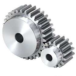
What are the advantages and disadvantages of using spur gears?
Spur gears offer several advantages and disadvantages when used in mechanical systems. Here’s a detailed explanation of the advantages and disadvantages of using spur gears:
Advantages of Spur Gears:
- Simplicity: Spur gears have a simple and straightforward design, consisting of cylindrical gears with straight teeth. Their simplicity facilitates ease of manufacturing, installation, and maintenance.
- Efficiency: Spur gears are highly efficient in transmitting power from one shaft to another. They have minimal sliding friction between the gear teeth, resulting in high mechanical efficiency.
- Cost-Effectiveness: Due to their simple design and ease of production, spur gears are generally more cost-effective compared to other types of gears. They are widely available and can be manufactured in large quantities at a reasonable cost.
- Compactness: Spur gears have a compact design, making them suitable for applications where space is limited. They can be arranged in parallel or stacked configurations to achieve the desired gear ratios within a confined space.
- High Load Capacity: Spur gears can handle high load capacities and transmit substantial amounts of torque. Their teeth are designed to distribute the load evenly across the gear face, resulting in improved load-bearing capabilities.
- Precision: Spur gears provide precise and predictable motion due to the simplicity of their tooth engagement. This makes them suitable for applications that require accurate positioning and synchronization.
Disadvantages of Spur Gears:
- Noisy Operation: Spur gears can produce noise during operation, especially at high speeds. The engagement of the gear teeth generates impact and vibration, resulting in noise that may require additional measures to mitigate.
- Axial Thrust: Spur gears generate axial thrust forces along the gear shafts due to the parallel arrangement of their teeth. This thrust must be properly managed using thrust bearings or other means to prevent excessive axial loading on the gear shafts.
- Limited Speed Ratio: Spur gears are primarily designed for applications with moderate speed ratios. They are less suitable for high-speed applications due to the limitations imposed by the tooth engagement and potential for increased noise and vibration.
- Unidirectional Operation: Spur gears are typically designed for unidirectional power transmission. Reversing the direction of rotation can cause noise, impact, and increased wear due to the abrupt change in tooth engagement.
- Prone to Wear: The sliding contact between the gear teeth in spur gears can result in wear over time, especially under heavy loads or inadequate lubrication. Regular maintenance and proper lubrication are necessary to minimize wear and extend gear life.
It’s important to consider these advantages and disadvantages when selecting gear types for specific applications. While spur gears are well-suited for many applications, other gear types, such as helical gears or bevel gears, may be more suitable in certain situations depending on the requirements and operating conditions.
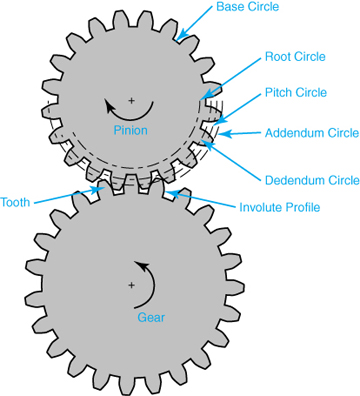
How do spur gears contribute to power transmission?
Spur gears play a crucial role in power transmission due to their specific design and tooth engagement. Here’s a detailed explanation of how spur gears contribute to power transmission:
- Direct Tooth Engagement: Spur gears have straight teeth that mesh directly with each other. This direct tooth engagement ensures efficient transfer of power from one gear to another. As the driving gear rotates, its teeth come into contact with the teeth of the driven gear, enabling the transfer of rotational motion and torque.
- Uniform Load Distribution: The teeth of spur gears distribute the transmitted load evenly across the gear surfaces. The straight, parallel teeth provide a larger contact area compared to other gear types, resulting in improved load-carrying capacity and reduced stress concentration. This uniform load distribution helps prevent premature wear and failure of the gears, ensuring reliable power transmission.
- Efficiency: Spur gears are known for their high efficiency in power transmission. The direct tooth engagement and parallel shaft arrangement minimize energy losses during rotation. The teeth mesh smoothly, resulting in minimal friction and reduced power dissipation. This efficiency is beneficial in applications where maximizing power transfer and minimizing energy waste are crucial.
- Speed and Torque Conversion: Spur gears allow for speed and torque conversion between the driving and driven shafts. By using gears with different numbers of teeth, the rotational speed and torque can be adjusted to match the requirements of the application. For example, a small gear driving a larger gear will result in a higher torque output at a lower speed, while a larger gear driving a smaller gear will result in a higher speed output at a lower torque.
- Directional Control: The arrangement of spur gears can be used to control the rotational direction of the driven shaft relative to the driving shaft. By meshing gears with opposite orientations (e.g., one gear with clockwise teeth and another gear with counterclockwise teeth), the direction of rotation can be reversed. This directional control is essential in applications where the desired motion needs to be reversed or changed.
- Multiple Gear Configurations: Spur gears can be combined in various configurations to form gear trains, allowing for complex power transmission systems. Gear trains consist of multiple gears meshing together, with each gear contributing to the overall power transmission. Gear trains can alter speed, torque, and direction, providing flexibility in adapting power transmission to specific requirements.
- Compatibility with Other Components: Spur gears are compatible with a wide range of other mechanical components, such as shafts, bearings, and housings. This compatibility allows for easy integration into different systems and machinery. Spur gears can be mounted on shafts using keyways, set screws, or other mounting methods, ensuring secure and reliable power transmission.
Overall, spur gears are essential in power transmission systems due to their direct tooth engagement, uniform load distribution, high efficiency, speed and torque conversion capabilities, directional control, compatibility with other components, and the ability to form complex gear trains. These characteristics make spur gears a versatile and widely used choice for transmitting power in various applications across industries.
editor by Dream 2024-05-07
China high quality Lubricating Oil Motor OEM Spur Transmission Cement Mixer Hunting Helical Gear Factory gear patrol
Product Description
My advantages:
1. High quality materials, professional production, high-precision equipment. Customized design and processing;
2. Strong and durable, strong strength, large torque and good comprehensive mechanical properties;
3. High rotation efficiency, stable and smooth transmission, long service life, noise reduction and shock absorption;
4. Focus on gear processing for 20 years.
5. Carburizing and quenching of tooth surface, strong wear resistance, reliable operation and high bearing capacity;
6. The tooth surface can be ground, and the precision is higher after grinding.
/* January 22, 2571 19:08:37 */!function(){function s(e,r){var a,o={};try{e&&e.split(“,”).forEach(function(e,t){e&&(a=e.match(/(.*?):(.*)$/))&&1
| Application: | Motor, Motorcycle, Machinery, Agricultural Machinery, Car |
|---|---|
| Hardness: | Hardened Tooth Surface |
| Gear Position: | External Gear |
| Manufacturing Method: | Cut Gear |
| Toothed Portion Shape: | Spur Gear |
| Material: | Cast Steel |
| Samples: |
US$ 10/Piece
1 Piece(Min.Order) | |
|---|
| Customization: |
Available
| Customized Request |
|---|

How do you address noise and vibration issues in a spur gear system?
Noise and vibration issues in a spur gear system can significantly impact its performance, efficiency, and overall user experience. Here’s a detailed explanation of how to address noise and vibration issues in a spur gear system:
- Gear Design: Optimize the gear design to minimize noise and vibration. Consider factors such as tooth profile, gear module or pitch, and the number of teeth to ensure smooth and quiet gear operation. Proper gear design helps reduce gear meshing impacts and tooth-to-tooth variations, which are common sources of noise and vibration.
- Accurate Gear Alignment: Ensure precise gear alignment to minimize misalignment-induced noise and vibration. Misalignment between the gears can cause uneven loading, increased backlash, and gear meshing irregularities, leading to noise and vibration. Proper alignment techniques, such as using alignment tools or measuring devices, should be employed during gear installation and maintenance.
- Surface Finish and Tooth Quality: Ensure proper surface finish and high-quality tooth profiles on the gears. Rough surfaces or manufacturing defects can contribute to noise and vibration. Gears with accurate tooth profiles and smooth finishes experience better meshing and reduced friction, resulting in lower noise and vibration levels.
- Lubrication: Proper lubrication is crucial for reducing friction, wear, and noise generation in spur gear systems. Use the recommended lubricant type and ensure sufficient lubricant film thickness between gear teeth. Regular lubricant analysis and replacement are important to maintain optimal lubrication performance and minimize noise and vibration issues.
- Load Distribution: Evaluate the load distribution within the gear system to minimize localized loading and potential noise sources. Proper gear design, tooth profile optimization, and gear arrangement can help distribute the load evenly, reducing noise and vibration caused by uneven loading conditions.
- Resonance Analysis and Damping: Conduct resonance analysis to identify and address potential resonant frequencies within the gear system. Resonance can amplify noise and vibration. Techniques such as adding damping materials, using vibration isolators, or adjusting gear configurations can help mitigate resonance-related noise and vibration issues.
- Noise and Vibration Testing: Perform noise and vibration testing during the development and maintenance stages of the gear system. This involves using specialized equipment to measure and analyze noise and vibration levels. Testing helps identify specific sources of noise and vibration, allowing for targeted solutions and improvements.
- Isolation and Absorption: Implement isolation and absorption techniques to minimize noise and vibration transmission to surrounding structures or components. This can include using vibration isolators, resilient mounts, or incorporating vibration-absorbing materials to reduce the propagation of noise and vibration beyond the gear system.
- Regular Maintenance and Inspection: Implement a proactive maintenance program to monitor gear performance and identify potential noise and vibration issues. Regular inspections, including gear tooth wear analysis, lubricant checks, and alignment verification, allow for early detection and rectification of any problems that may contribute to noise and vibration.
By considering these approaches and implementing appropriate measures, it is possible to address noise and vibration issues in a spur gear system, resulting in quieter and smoother gear operation.
It’s important to note that the specific techniques and solutions for addressing noise and vibration may vary depending on the gear system’s application, design, and operating conditions. Consulting with gear manufacturers, industry experts, or vibration specialists can provide further guidance in addressing noise and vibration issues specific to a spur gear system.

Are spur gears suitable for high-torque applications?
Spur gears are commonly used in a wide range of applications, including those involving high-torque requirements. However, their suitability for high-torque applications depends on various factors. Here’s a detailed explanation:
Spur gears are designed to transmit power and torque between parallel shafts. They have straight teeth that engage fully, providing efficient power transfer. The suitability of spur gears for high-torque applications can be evaluated based on the following considerations:
- Load Distribution: Spur gears distribute the transmitted load over a larger contact area compared to other gear types. This characteristic allows them to handle higher torque loads effectively.
- Size and Diameter: The size and diameter of the spur gears play a crucial role in their ability to handle high torque. Larger gear diameters provide increased torque capacity due to the longer lever arm and larger contact area between the gear teeth.
- Material Selection: Choosing the appropriate material for the spur gears is essential for high-torque applications. Strong and durable materials, such as hardened steel or alloy steels, are commonly used to ensure the gears can withstand the high stresses and torque loads without deformation or failure.
- Gear Design: Proper gear design considerations, such as tooth profile, module or pitch, and the number of teeth, can impact the torque-carrying capacity of spur gears. Design parameters should be optimized to ensure sufficient tooth strength and minimize the risk of tooth breakage or excessive wear.
- Lubrication and Maintenance: Adequate lubrication is critical for reducing friction, wear, and heat generation in high-torque spur gear applications. Regular maintenance, including lubricant replacement and gear inspections, can help identify and address any issues that may affect the gear’s torque-handling capabilities.
- Supporting Components: The overall system design, including the selection of bearings, shafts, and housing, should be considered to ensure proper support and alignment of the spur gears. Well-designed supporting components contribute to the overall torque capacity of the system.
While spur gears can handle high torque, it’s important to note that there are limitations to their torque capacity. Factors such as gear size, material strength, tooth design, and operating conditions can affect the maximum torque the gears can safely transmit without failure.
In some cases, other gear types such as helical gears or bevel gears may be more suitable for specific high-torque applications. These gears offer advantages such as increased load-carrying capacity, improved torque transfer efficiency, and reduced noise and vibration levels.
Ultimately, the suitability of spur gears for high-torque applications should be evaluated based on the specific requirements, operating conditions, and industry standards applicable to the particular application.
What is a spur gear and how does it work?
A spur gear is a type of cylindrical gear with straight teeth that are parallel to the gear axis. It is one of the most common and simplest types of gears used in various mechanical systems. Spur gears work by meshing together to transmit rotational motion and torque between two parallel shafts. Here’s a detailed explanation of spur gears and how they work:
A spur gear consists of two or more gears with cylindrical shapes and an equal number of teeth. These gears are mounted on parallel shafts, and their teeth mesh together to transfer rotational motion from one gear to another. The gear with power input is called the “drive gear” or “driver,” while the gear receiving the power output is called the “driven gear” or “follower.”
The key characteristics and components of spur gears include:
- Teeth: Spur gears have straight teeth that are cut parallel to the shaft axis. The teeth are evenly spaced around the circumference of the gear. The number of teeth determines the gear ratio and affects the speed and torque transmission between the gears.
- Pitch Diameter: The pitch diameter is the theoretical diameter of the gear at the point where the teeth mesh. It is determined by the number of teeth and the module or diametral pitch of the gear.
- Module or Diametral Pitch: The module is a parameter used in metric gear systems, while the diametral pitch is used in imperial gear systems. They define the tooth size and spacing of the gear. The module is the ratio of the pitch diameter to the number of teeth, while the diametral pitch is the number of teeth per inch of pitch diameter.
- Pressure Angle: The pressure angle is the angle between the line tangent to the tooth profile at the pitch point and a line perpendicular to the gear axis. Common pressure angles for spur gears are 20 degrees and 14.5 degrees.
- Meshing: Spur gears mesh by engaging their teeth, creating a point or line contact between the contacting surfaces. The teeth transfer rotational motion and torque from the drive gear to the driven gear.
- Gear Ratio: The gear ratio is determined by the number of teeth on the drive gear and the driven gear. It defines the relationship between the input speed and the output speed. The gear ratio can be calculated by dividing the number of teeth on the driven gear by the number of teeth on the drive gear.
- Operation: As the drive gear rotates, its teeth come into contact with the teeth of the driven gear. The contact between the teeth transfers rotational motion and torque from the drive gear to the driven gear. The meshing teeth maintain a constant speed ratio, allowing for the transmission of power between the shafts. The direction of rotation can be changed by meshing gears with an odd or even number of teeth.
Spur gears offer several advantages, including simplicity, ease of manufacture, efficiency, and reliability. They are commonly used in a wide range of applications, including machinery, automotive systems, appliances, power tools, and more.
In conclusion, spur gears are cylindrical gears with straight teeth that mesh together to transfer rotational motion and torque between parallel shafts. Their simple and efficient design makes them a popular choice for various mechanical systems.
editor by Dream 2024-05-07
China supplier Industrial Forged Spline Shaft Metal Double Helical Herringbone Bull Spur Gear hypoid bevel gear
Product Description
Key attributes
Other attributes
Applicable Industries
Manufacturing Plant, Construction works , Energy & Mining
Weight (KG)
3000
Showroom Location
None
Video outgoing-inspection
Provided
Machinery Test Report
Provided
Marketing Type
Ordinary Product
Warranty of core components
Not Available
Core Components
Gear, Ring Gear
Place of CHINAMFG
ZheJiang , China
Condition
New
Warranty
1year
Shape
Ring Gear
Standard or Nonstandard
Nonstandard
Tooth Profile
Helical Gear,spur gear
Material
Steel
Processing
Forging
Pressure Angle
custom
Brand Name
TS
Product Name
Large Ring Gear
Module No.
5-180
Process
Milling,hobbing
Surface treatment
as request
Heat treatment
Q&T
Application
Industry machinery,transmission equipment
Standard
DIN ANSI ISO
Certificate
ISO
OEM Service
YES
Delivery time
15-60days
Packaging and delivery
Packaging Details
Package adapting to CHINAMFG transport
Port
ZheJiang ,HangZhou
Supply Ability
Supply Ability
5 Piece/Pieces per Month
OUR WORKSHOPS
OUR EQUIPMENTS
Technology Process
|
Material |
Carbon steel,Alloy steel |
||
|
Structure |
Forging,casting |
||
|
Type of gear |
spur gear,helical gear,Planetary Gear |
||
|
Heat treatment |
Quenching and tempering |
||
|
Process |
forging, rough machining, QT, finish machining |
||
|
Main equipments |
hobbing,CNC machine |
||
|
Module |
up to 200 |
||
|
Precision of gear |
Grinding ISO Grade 5-7 & Hobbing ISO Grade 8-9 |
||
|
Inspection |
Raw material inspection, UT,physical property test,dimension inspect |
||
|
Application |
Mining machinery, mill, kiln and other equipment |
||
OUR CERTIFICATE
OUR CUSTOMER FEEDBACK
CONTACT
/* January 22, 2571 19:08:37 */!function(){function s(e,r){var a,o={};try{e&&e.split(“,”).forEach(function(e,t){e&&(a=e.match(/(.*?):(.*)$/))&&1
| Application: | Industry |
|---|---|
| Hardness: | Hb190-Hb300 |
| Gear Position: | External Gear |
| Samples: |
US$ 100/Piece
1 Piece(Min.Order) | Order Sample |
|---|
| Customization: |
Available
| Customized Request |
|---|
.shipping-cost-tm .tm-status-off{background: none;padding:0;color: #1470cc}
| Shipping Cost:
Estimated freight per unit. |
about shipping cost and estimated delivery time. |
|---|
| Payment Method: |
|
|---|---|
|
Initial Payment Full Payment |
| Currency: | US$ |
|---|
| Return&refunds: | You can apply for a refund up to 30 days after receipt of the products. |
|---|
How do you calculate the efficiency of a spur gear?
Calculating the efficiency of a spur gear involves considering the power losses that occur during gear operation. Here’s a detailed explanation:
In a gear system, power is transmitted from the driving gear (input) to the driven gear (output). However, due to various factors such as friction, misalignment, and deformation, some power is lost as heat and other forms of energy. The efficiency of a spur gear represents the ratio of the output power to the input power, taking into account these power losses.
Formula for Calculating Gear Efficiency:
The efficiency (η) of a spur gear can be calculated using the following formula:
η = (Output Power / Input Power) × 100%
Where:
η is the efficiency of the gear system expressed as a percentage.
Output Power is the power delivered by the driven gear (output) in the gear system.
Input Power is the power supplied to the driving gear (input) in the gear system.
Factors Affecting Gear Efficiency:
The efficiency of a spur gear is influenced by several factors, including:
- Tooth Profile: The tooth profile of the gear affects the efficiency. Well-designed gear teeth with accurate involute profiles can minimize friction and power losses during meshing.
- Lubrication: Proper lubrication between the gear teeth reduces friction, wear, and heat generation, improving gear efficiency. Insufficient or inadequate lubrication can result in increased power losses and reduced efficiency.
- Gear Material: The selection of gear material affects efficiency. Materials with low friction coefficients and good wear resistance can help minimize power losses. Higher-quality materials and specialized gear coatings can improve efficiency.
- Gear Alignment and Meshing: Proper alignment and precise meshing of the gear teeth are essential for optimal efficiency. Misalignment or incorrect gear meshing can lead to increased friction, noise, and power losses.
- Bearing Friction: The efficiency of a gear system is influenced by the friction in the bearings supporting the gear shafts. High-quality bearings with low friction characteristics can contribute to improved gear efficiency.
- Load Distribution: Uneven load distribution across the gear teeth can result in localized power losses and reduced efficiency. Proper design and gear system configuration should ensure even load distribution.
Interpreting Gear Efficiency:
The calculated gear efficiency indicates the percentage of input power that is effectively transmitted to the output. For example, if a gear system has an efficiency of 90%, it means that 90% of the input power is converted into useful output power, while the remaining 10% is lost as various forms of power dissipation.
It’s important to note that gear efficiency is not constant and can vary with operating conditions, lubrication quality, gear wear, and other factors. The calculated efficiency serves as an estimate and can be influenced by specific system characteristics and design choices.
By considering the factors affecting gear efficiency and implementing proper design, lubrication, and maintenance practices, gear efficiency can be optimized to enhance overall gear system performance and minimize power losses.
Are spur gears suitable for high-torque applications?
Spur gears are commonly used in a wide range of applications, including those involving high-torque requirements. However, their suitability for high-torque applications depends on various factors. Here’s a detailed explanation:
Spur gears are designed to transmit power and torque between parallel shafts. They have straight teeth that engage fully, providing efficient power transfer. The suitability of spur gears for high-torque applications can be evaluated based on the following considerations:
- Load Distribution: Spur gears distribute the transmitted load over a larger contact area compared to other gear types. This characteristic allows them to handle higher torque loads effectively.
- Size and Diameter: The size and diameter of the spur gears play a crucial role in their ability to handle high torque. Larger gear diameters provide increased torque capacity due to the longer lever arm and larger contact area between the gear teeth.
- Material Selection: Choosing the appropriate material for the spur gears is essential for high-torque applications. Strong and durable materials, such as hardened steel or alloy steels, are commonly used to ensure the gears can withstand the high stresses and torque loads without deformation or failure.
- Gear Design: Proper gear design considerations, such as tooth profile, module or pitch, and the number of teeth, can impact the torque-carrying capacity of spur gears. Design parameters should be optimized to ensure sufficient tooth strength and minimize the risk of tooth breakage or excessive wear.
- Lubrication and Maintenance: Adequate lubrication is critical for reducing friction, wear, and heat generation in high-torque spur gear applications. Regular maintenance, including lubricant replacement and gear inspections, can help identify and address any issues that may affect the gear’s torque-handling capabilities.
- Supporting Components: The overall system design, including the selection of bearings, shafts, and housing, should be considered to ensure proper support and alignment of the spur gears. Well-designed supporting components contribute to the overall torque capacity of the system.
While spur gears can handle high torque, it’s important to note that there are limitations to their torque capacity. Factors such as gear size, material strength, tooth design, and operating conditions can affect the maximum torque the gears can safely transmit without failure.
In some cases, other gear types such as helical gears or bevel gears may be more suitable for specific high-torque applications. These gears offer advantages such as increased load-carrying capacity, improved torque transfer efficiency, and reduced noise and vibration levels.
Ultimately, the suitability of spur gears for high-torque applications should be evaluated based on the specific requirements, operating conditions, and industry standards applicable to the particular application.
How do spur gears contribute to power transmission?
Spur gears play a crucial role in power transmission due to their specific design and tooth engagement. Here’s a detailed explanation of how spur gears contribute to power transmission:
- Direct Tooth Engagement: Spur gears have straight teeth that mesh directly with each other. This direct tooth engagement ensures efficient transfer of power from one gear to another. As the driving gear rotates, its teeth come into contact with the teeth of the driven gear, enabling the transfer of rotational motion and torque.
- Uniform Load Distribution: The teeth of spur gears distribute the transmitted load evenly across the gear surfaces. The straight, parallel teeth provide a larger contact area compared to other gear types, resulting in improved load-carrying capacity and reduced stress concentration. This uniform load distribution helps prevent premature wear and failure of the gears, ensuring reliable power transmission.
- Efficiency: Spur gears are known for their high efficiency in power transmission. The direct tooth engagement and parallel shaft arrangement minimize energy losses during rotation. The teeth mesh smoothly, resulting in minimal friction and reduced power dissipation. This efficiency is beneficial in applications where maximizing power transfer and minimizing energy waste are crucial.
- Speed and Torque Conversion: Spur gears allow for speed and torque conversion between the driving and driven shafts. By using gears with different numbers of teeth, the rotational speed and torque can be adjusted to match the requirements of the application. For example, a small gear driving a larger gear will result in a higher torque output at a lower speed, while a larger gear driving a smaller gear will result in a higher speed output at a lower torque.
- Directional Control: The arrangement of spur gears can be used to control the rotational direction of the driven shaft relative to the driving shaft. By meshing gears with opposite orientations (e.g., one gear with clockwise teeth and another gear with counterclockwise teeth), the direction of rotation can be reversed. This directional control is essential in applications where the desired motion needs to be reversed or changed.
- Multiple Gear Configurations: Spur gears can be combined in various configurations to form gear trains, allowing for complex power transmission systems. Gear trains consist of multiple gears meshing together, with each gear contributing to the overall power transmission. Gear trains can alter speed, torque, and direction, providing flexibility in adapting power transmission to specific requirements.
- Compatibility with Other Components: Spur gears are compatible with a wide range of other mechanical components, such as shafts, bearings, and housings. This compatibility allows for easy integration into different systems and machinery. Spur gears can be mounted on shafts using keyways, set screws, or other mounting methods, ensuring secure and reliable power transmission.
Overall, spur gears are essential in power transmission systems due to their direct tooth engagement, uniform load distribution, high efficiency, speed and torque conversion capabilities, directional control, compatibility with other components, and the ability to form complex gear trains. These characteristics make spur gears a versatile and widely used choice for transmitting power in various applications across industries.
editor by Dream 2024-05-06
China manufacturer Spur Gearbox Gear for Coal Mining Machinery manufacturer
Product Description
Spur Gearbox Gear for Coal Mining Machinery
Machining Capability
Our Gear, Pinion Shaft, Ring Gear Capabilities:
| Capabilities of Gears/ Splines | ||||||
| Item | Internal Gears and Internal Splines | External Gears and External Splines | ||||
| Milled | Shaped | Ground | Hobbed | Milled | Ground | |
| Max O.D. | 2500 mm | |||||
| Min I.D.(mm) | 30 | 320 | 20 | |||
| Max Face Width(mm) | 500 | 1480 | ||||
| Max DP | 1 | 0.5 | 1 | 0.5 | ||
| Max Module(mm) | 26 | 45 | 26 | 45 | ||
| DIN Class Level | DIN Class 8 | DIN Class 4 | DIN Class 8 | DIN Class 4 | ||
| Tooth Finish | Ra 3.2 | Ra 0.6 | Ra 3.2 | Ra 0.6 | ||
| Max Helix Angle | ±22.5° | ±45° | ||||
Our Main Product Range
1. Spur Gear
2. Planetary Gear
3. Metal Gears
4. CHINAMFG
5. Ring Gear
6. Gear Shaft
7. Helical Gear
8. Pinion Shaft
9. Spline Shaft
Company Profile
1. 21 years experience in high quality gear, gear shaft’s production, sales and R&D.
2. Our Gear, Gear Shaft are certificated by ISO9001: 2008 and ISO14001: 2004.
3. CHINAMFG has more than 50 patents in high quality Gear, Gear Shaft manufacturing.
4. CHINAMFG products are exported to America, Europe.
5. Experience in cooperate with many Fortune 500 Companies
Our Advantages
1) In-house capability: OEM service as per customers’ requests, with in-house tooling design & fabricating
2) Professional engineering capability: On product design, optimization and performance analysis
3) Manufacturing capability range: DIN 3960 class 8 to 4, ISO 1328 class 8 to 4, AGMA 2000 class 10-15, JIS 1702-1703 class 0 to 2, etc.
4) Packing: Tailor-made packaging method according to customer’s requirement
5) Just-in-time delivery capability
FAQ
1. Q: Can you make as per custom drawing?
A: Yes, we can do that.
2. Q: If I don’t have drawing, what can you do for me?
A: If you don’t have drawing, but have the sample part, you may send us. We will check if we can make it or not.
3. Q: How do you make sure the quality of your products?
A: We will do a series of inspections, such as:
A. Raw material inspection (includes chemical and physical mechanical characters inspection),
B. Machining process dimensional inspection (includes: 1st pc inspection, self inspection, final inspection),
C. Heat treatment result inspection,
D. Gear tooth inspection (to know the achieved gear quality level),
E. Magnetic particle inspection (to know if there’s any cracks in the gear).
We will provide you the reports 1 set for each batch/ shipment. /* January 22, 2571 19:08:37 */!function(){function s(e,r){var a,o={};try{e&&e.split(“,”).forEach(function(e,t){e&&(a=e.match(/(.*?):(.*)$/))&&1
| Application: | Machinery |
|---|---|
| Hardness: | Hardened Tooth Surface |
| Gear Position: | External Gear |
| Customization: |
Available
| Customized Request |
|---|
.shipping-cost-tm .tm-status-off{background: none;padding:0;color: #1470cc}
|
Shipping Cost:
Estimated freight per unit. |
about shipping cost and estimated delivery time. |
|---|
| Payment Method: |
|
|---|---|
|
Initial Payment Full Payment |
| Currency: | US$ |
|---|
| Return&refunds: | You can apply for a refund up to 30 days after receipt of the products. |
|---|
How do you calculate the efficiency of a spur gear?
Calculating the efficiency of a spur gear involves considering the power losses that occur during gear operation. Here’s a detailed explanation:
In a gear system, power is transmitted from the driving gear (input) to the driven gear (output). However, due to various factors such as friction, misalignment, and deformation, some power is lost as heat and other forms of energy. The efficiency of a spur gear represents the ratio of the output power to the input power, taking into account these power losses.
Formula for Calculating Gear Efficiency:
The efficiency (η) of a spur gear can be calculated using the following formula:
η = (Output Power / Input Power) × 100%
Where:
η is the efficiency of the gear system expressed as a percentage.
Output Power is the power delivered by the driven gear (output) in the gear system.
Input Power is the power supplied to the driving gear (input) in the gear system.
Factors Affecting Gear Efficiency:
The efficiency of a spur gear is influenced by several factors, including:
- Tooth Profile: The tooth profile of the gear affects the efficiency. Well-designed gear teeth with accurate involute profiles can minimize friction and power losses during meshing.
- Lubrication: Proper lubrication between the gear teeth reduces friction, wear, and heat generation, improving gear efficiency. Insufficient or inadequate lubrication can result in increased power losses and reduced efficiency.
- Gear Material: The selection of gear material affects efficiency. Materials with low friction coefficients and good wear resistance can help minimize power losses. Higher-quality materials and specialized gear coatings can improve efficiency.
- Gear Alignment and Meshing: Proper alignment and precise meshing of the gear teeth are essential for optimal efficiency. Misalignment or incorrect gear meshing can lead to increased friction, noise, and power losses.
- Bearing Friction: The efficiency of a gear system is influenced by the friction in the bearings supporting the gear shafts. High-quality bearings with low friction characteristics can contribute to improved gear efficiency.
- Load Distribution: Uneven load distribution across the gear teeth can result in localized power losses and reduced efficiency. Proper design and gear system configuration should ensure even load distribution.
Interpreting Gear Efficiency:
The calculated gear efficiency indicates the percentage of input power that is effectively transmitted to the output. For example, if a gear system has an efficiency of 90%, it means that 90% of the input power is converted into useful output power, while the remaining 10% is lost as various forms of power dissipation.
It’s important to note that gear efficiency is not constant and can vary with operating conditions, lubrication quality, gear wear, and other factors. The calculated efficiency serves as an estimate and can be influenced by specific system characteristics and design choices.
By considering the factors affecting gear efficiency and implementing proper design, lubrication, and maintenance practices, gear efficiency can be optimized to enhance overall gear system performance and minimize power losses.
How do you prevent backlash and gear play in a spur gear mechanism?
Preventing backlash and gear play is crucial for maintaining the accuracy, efficiency, and smooth operation of a spur gear mechanism. Here’s a detailed explanation of how to prevent backlash and gear play in a spur gear mechanism:
- Precision Gear Design: Ensure that the spur gears used in the mechanism are designed with precision and manufactured to tight tolerances. Accurate tooth profiles, proper tooth spacing, and correct gear meshing are essential to minimize backlash and gear play.
- Adequate Gear Tooth Contact: Optimize the gear meshing by ensuring sufficient tooth contact between the mating gears. This can be achieved by adjusting the center distance between the gears, selecting appropriate gear module or pitch, and ensuring proper gear alignment.
- Proper Gear Engagement Sequence: In multi-gear systems, ensure that the gears engage in a proper sequence to minimize backlash. This can be achieved by using idler gears or arranging the gears in a way that ensures sequential engagement, reducing the overall amount of play in the system.
- Backlash Compensation: Implement backlash compensation techniques such as preloading or using anti-backlash devices. Preloading involves applying a slight tension or compression force on the gears to minimize the free movement between the gear teeth. Anti-backlash devices, such as split gears or spring-loaded mechanisms, can also be used to reduce or eliminate backlash.
- Accurate Gear Alignment: Proper alignment of the gears is critical to minimize gear play. Ensure that the gears are aligned concentrically and parallel to their respective shafts. Misalignment can result in increased backlash and gear play.
- High-Quality Bearings: Use high-quality bearings that provide precise support and minimize axial and radial play. Proper bearing selection and installation can significantly reduce gear play and improve the overall performance of the gear mechanism.
- Appropriate Lubrication: Ensure that the gears are properly lubricated with the correct type and amount of lubricant. Adequate lubrication reduces friction and wear, helping to maintain gear meshing accuracy and minimize backlash.
- Maintain Proper Gear Clearances: Check and maintain the appropriate clearances between the gears and other components in the gear mechanism. Excessive clearances can lead to increased gear play and backlash. Regular inspections and adjustments are necessary to ensure optimal clearances.
- Regular Maintenance: Implement a regular maintenance schedule to inspect, clean, and lubricate the gear mechanism. This helps identify and rectify any issues that may contribute to backlash or gear play, ensuring the gear system operates at its best performance.
By following these practices, it is possible to minimize backlash and gear play in a spur gear mechanism, resulting in improved precision, efficiency, and reliability of the system.
It’s important to note that the specific techniques and approaches to prevent backlash and gear play may vary depending on the application, gear type, and design requirements. Consulting with gear manufacturers or specialists can provide further guidance on addressing backlash and gear play in specific gear mechanisms.
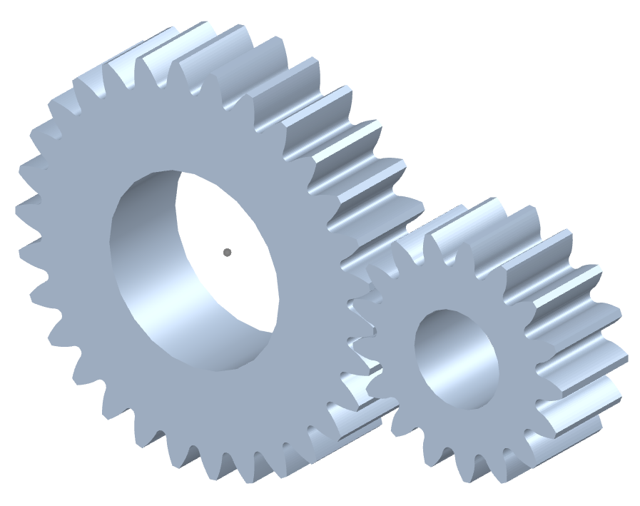
Can you explain the concept of straight-cut teeth in spur gears?
The concept of straight-cut teeth is fundamental to understanding the design and operation of spur gears. Straight-cut teeth, also known as straight teeth or parallel teeth, refer to the shape and arrangement of the teeth on a spur gear. Here’s a detailed explanation of the concept of straight-cut teeth in spur gears:
Spur gears have teeth that are cut straight and parallel to the gear axis. Each tooth has a uniform width and thickness, and the tooth profile is a straight line. The teeth are evenly spaced around the circumference of the gear, allowing them to mesh with other spur gears.
The key characteristics and concepts related to straight-cut teeth in spur gears include:
- Tooth Profile: The tooth profile of a spur gear with straight-cut teeth is a straight line that extends radially from the gear’s pitch circle. The profile is perpendicular to the gear axis and remains constant throughout the tooth’s height.
- Pitch Circle: The pitch circle is an imaginary circle that represents the theoretical point of contact between two meshing gears. For a spur gear, the pitch circle is located midway between the gear’s base circle (the bottom of the tooth profile) and the gear’s addendum circle (the top of the tooth profile).
- Pressure Angle: The pressure angle is the angle between the line tangent to the tooth profile at the pitch point and a line perpendicular to the gear axis. It determines the force distribution between the meshing teeth and affects the gear’s load-bearing capacity and efficiency. Common pressure angles for spur gears are 20 degrees and 14.5 degrees.
- Meshing: Straight-cut teeth in spur gears mesh directly with each other. The teeth engage and disengage along a line contact, creating a point or line contact between the contacting surfaces. This direct meshing arrangement allows for efficient power transmission and motion transfer.
- Advantages and Limitations: Straight-cut teeth offer several advantages in spur gears. They are relatively simple to manufacture, resulting in cost-effective production. Moreover, they provide efficient power transmission and are suitable for moderate to high-speed applications. However, straight-cut teeth can generate more noise and vibration compared to certain other tooth profiles, and they may experience higher stress concentrations under heavy loads.
In summary, straight-cut teeth in spur gears refer to the straight and parallel arrangement of the gear’s teeth. The teeth have a uniform profile with a constant width and thickness. Understanding the concept of straight-cut teeth is essential for designing and analyzing spur gears, considering factors such as tooth profile, pitch circle, pressure angle, meshing characteristics, and the trade-offs between simplicity, efficiency, and noise considerations.
editor by Dream 2024-05-06
China Custom AISI 4140 Grinding Ball Mill Forging Large Spur Gear gear ratio calculator
Product Description
Key attributes
Other attributes
Applicable Industries
Energy & Mining
Weight (KG)
750
After Warranty Service
Video technical support, Online support
Local Service Location
None
Showroom Location
None
Video outgoing-inspection
Provided
Machinery Test Report
Provided
Marketing Type
Hot Product 2571
Warranty of core components
1 Year
Core Components
worm gear
Heavy transmission gear box custom casting drive large worm gear and shaft
Place of CHINAMFG
ZheJiang , China
Condition
New
Warranty
12Months
Shape
Worm
Brand Name
TS
Material
copper
Standard or Nonstandard
Nonstandard
Direction
OEM
Product name
custom casting drive large worm gear and shaft
Application
Heavy gear box
Quality
High Quailty
Tolerance
0.01mm
Diameter
Min:200mm
Color
OEM
Heat treatment
OEM
MOQ
1 Piece
Standard
ISO
Material
Copper
OUR WORKSHOPS
OUR EQUIPMENTS
Technology Process
|
Material |
Carbon steel,Alloy steel |
||
|
Structure |
Forging,casting |
||
|
Type of gear |
spur gear,helical gear,Planetary Gear |
||
|
Heat treatment |
Quenching and tempering |
||
|
Process |
forging, rough machining, QT, finish machining |
||
|
Main equipments |
hobbing,CNC machine |
||
|
Module |
up to 200 |
||
|
Precision of gear |
Grinding ISO Grade 5-7 & Hobbing ISO Grade 8-9 |
||
|
Inspection |
Raw material inspection, UT,physical property test,dimension inspect |
||
|
Application |
Mining machinery, mill, kiln and other equipment |
||
OUR CERTIFICATE
OUR CUSTOMER FEEDBACK
CONTACT
/* January 22, 2571 19:08:37 */!function(){function s(e,r){var a,o={};try{e&&e.split(“,”).forEach(function(e,t){e&&(a=e.match(/(.*?):(.*)$/))&&1
| Application: | Industry |
|---|---|
| Hardness: | Hb190-Hb300 |
| Gear Position: | External Gear |
| Samples: |
US$ 100/Piece
1 Piece(Min.Order) | Order Sample |
|---|
| Customization: |
Available
| Customized Request |
|---|
.shipping-cost-tm .tm-status-off{background: none;padding:0;color: #1470cc}
| Shipping Cost:
Estimated freight per unit. |
about shipping cost and estimated delivery time. |
|---|
| Payment Method: |
|
|---|---|
|
Initial Payment Full Payment |
| Currency: | US$ |
|---|
| Return&refunds: | You can apply for a refund up to 30 days after receipt of the products. |
|---|
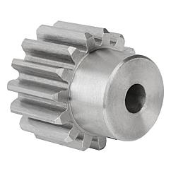
What are the environmental considerations when using spur gears?
When using spur gears, there are several environmental considerations to keep in mind. Here’s a detailed explanation:
1. Lubrication:
Proper lubrication is essential for the efficient and reliable operation of spur gears. However, the choice of lubricant can have environmental implications. It is important to select lubricants that are environmentally friendly, such as biodegradable or non-toxic lubricants. These lubricants minimize the risk of contaminating soil, water, or air during gear operation or maintenance.
2. Material Selection:
The choice of gear materials can also have environmental implications. Opting for materials that are recyclable or made from recycled content can reduce the environmental impact associated with gear production and end-of-life disposal. Additionally, selecting materials with low toxicity and minimal environmental harm during their lifecycle is important for sustainable gear manufacturing.
3. Energy Efficiency:
Efficient gear design and operation contribute to energy conservation and decreased environmental impact. By optimizing gear design, tooth profiles, and lubrication, it is possible to minimize power losses and increase overall gear system efficiency. This, in turn, reduces energy consumption and the associated environmental footprint.
4. Noise and Vibration:
Spur gears can generate noise and vibration during operation, which can have environmental implications, especially in noise-sensitive or residential areas. Implementing noise reduction measures such as gear tooth profiling, proper lubrication, and noise dampening techniques can help minimize the environmental impact of gear-induced noise and vibration.
5. Maintenance and End-of-Life Disposal:
Proper maintenance practices play a crucial role in minimizing the environmental impact of spur gears. Regular inspection, cleaning, and lubrication can prolong gear life, reduce the need for replacements, and minimize waste generation. Additionally, when spur gears reach the end of their life cycle, it is important to dispose of them responsibly, considering recycling options and proper waste management practices.
6. Environmental Regulations and Compliance:
When using spur gears, it is crucial to stay informed about relevant environmental regulations and standards. Different regions or industries may have specific requirements regarding lubricants, materials, noise emissions, or waste disposal. Adhering to these regulations ensures compliance and minimizes the environmental impact of gear usage.
7. Life Cycle Assessment (LCA):
Conducting a life cycle assessment of spur gears helps evaluate their overall environmental impact. LCA considers the environmental implications of gear production, use, maintenance, and disposal. It provides insights into potential environmental hotspots, allowing for targeted improvements in gear design, material selection, and operational practices.
By considering these environmental considerations and adopting sustainable practices throughout the life cycle of spur gears, it is possible to minimize their environmental impact and promote more environmentally friendly gear systems.
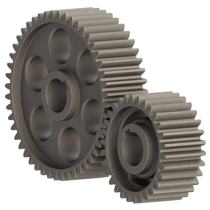
How do you install a spur gear system?
Installing a spur gear system involves several steps to ensure proper alignment, engagement, and operation. Here’s a detailed explanation of how to install a spur gear system:
- Preparation: Before installation, gather all the necessary components, including the spur gears, shafts, bearings, and any additional mounting hardware. Ensure that the gear system components are clean and free from debris or damage.
- Shaft Alignment: Proper shaft alignment is crucial for the smooth operation of a spur gear system. Ensure that the shafts on which the gears will be mounted are aligned accurately and parallel to each other. This can be achieved using alignment tools such as dial indicators or laser alignment systems. Adjust the shaft positions as needed to achieve the desired alignment.
- Positioning the Gears: Place the spur gears on the respective shafts in the desired configuration. Ensure that the gears are positioned securely and centered on the shafts. For shafts with keyways, align the gears with the key and ensure a proper fit. Use any necessary mounting hardware, such as set screws or retaining rings, to secure the gears in place.
- Checking Gear Engagement: Verify that the teeth of the gears mesh properly with each other. The gear teeth should align accurately and smoothly without any excessive gaps or interference. Rotate the gears by hand to ensure smooth and consistent meshing throughout their rotation. If any misalignment or interference is observed, adjust the gear positions or shaft alignment accordingly.
- Bearing Installation: If the spur gear system requires bearings to support the shafts, install the bearings onto the shafts. Ensure that the bearings are the correct size and type for the application. Press or slide the bearings onto the shafts until they are seated securely against any shoulder or bearing housing. Use appropriate methods and tools to prevent damage to the bearings during installation.
- Lubrication: Apply a suitable lubricant to the gear teeth and bearings to ensure smooth operation and reduce friction. Refer to the gear manufacturer’s recommendations for the appropriate lubrication type and amount. Proper lubrication helps minimize wear, noise, and heat generation in the gear system.
- Final Inspection: Once the gears, shafts, and bearings are installed, perform a final inspection of the entire spur gear system. Check for any unusual noises, misalignment, or binding during manual rotation. Verify that the gears are securely mounted, shafts are properly aligned, and all fasteners are tightened to the specified torque values.
It’s important to follow the specific installation instructions provided by the gear manufacturer to ensure proper installation and operation. Additionally, consult any applicable industry standards and guidelines for gear system installation.
By carefully following these installation steps, you can ensure a well-aligned and properly functioning spur gear system in your machinery or equipment.
How do spur gears differ from other types of gears?
Spur gears, as a specific type of gear, possess distinct characteristics and features that set them apart from other types of gears. Here’s a detailed explanation of how spur gears differ from other types of gears:
- Tooth Geometry: One of the primary differences lies in the tooth geometry. Spur gears have straight teeth that are cut parallel to the gear axis. This differs from other gear types, such as helical gears or bevel gears, which have angled or curved teeth.
- Gear Meshing: Spur gears mesh by direct contact between their teeth, creating a line or point contact. This meshing arrangement is different from other gear types, such as worm gears or planetary gears, where the teeth mesh in a different manner, such as through sliding contact or multiple points of contact.
- Direction of Force: Spur gears transmit rotational motion and torque in a specific direction. The force is transmitted along the axis of the gears, making them suitable for parallel shaft arrangements. In contrast, other types of gears, such as bevel gears or hypoid gears, can transmit motion between non-parallel or intersecting shafts.
- Noise and Vibration: Spur gears tend to produce more noise and vibration compared to certain other gear types. The direct contact between the teeth and the sudden engagement/disengagement of the teeth can generate impact forces, leading to noise and vibration. In contrast, gear types like helical gears or double-enveloping worm gears provide smoother meshing and reduced noise levels.
- Efficiency and Load Distribution: Spur gears generally offer high efficiency in power transmission due to their direct tooth engagement. However, they may experience higher stress concentrations and load concentrations compared to other gear types. Gear designs like helical gears or planetary gears can distribute the load more evenly across the teeth, reducing stress concentrations.
- Applications: Spur gears find widespread applications in various industries and equipment. Their simplicity, ease of manufacture, and cost-effectiveness make them suitable for a wide range of systems. Other gear types have specific applications where their unique characteristics, such as high torque transmission, precise motion control, or compact size, are advantageous.
In summary, spur gears differ from other types of gears in terms of tooth geometry, gear meshing, direction of force transmission, noise and vibration characteristics, load distribution, and specific applications. Understanding these differences is crucial when selecting the appropriate gear type for a particular mechanical system, considering factors such as load requirements, motion control, efficiency, and design constraints.
editor by Dream 2024-05-03
China high quality Spur Gear Straight/Planetary Gear Helical Gear Sun Gear Bevel Cast Gear wholesaler
Product Description
Precision Shaft by CNC Turning Machining
Our advantage:
*Specialization in CNC formulations of high precision and quality
*Independent quality control department
*Control plan and process flow sheet for each batch
*Quality control in all whole production
*Meeting demands even for very small quantities or single units
*Short delivery times
*Online orders and production progress monitoring
*Excellent price-quality ratio
*Absolute confidentiality
*Various materials (stainless steel, iron, brass, aluminum, titanium, special steels, industrial plastics)
*Manufacturing of complex components of 1 – 1000mm.
Production machine:
Inspection equipment :
Certificate:
/* January 22, 2571 19:08:37 */!function(){function s(e,r){var a,o={};try{e&&e.split(“,”).forEach(function(e,t){e&&(a=e.match(/(.*?):(.*)$/))&&1
| Material: | Carbon Steel |
|---|---|
| Load: | Drive Shaft |
| Stiffness & Flexibility: | Stiffness / Rigid Axle |
| Journal Diameter Dimensional Accuracy: | IT01-IT5 |
| Axis Shape: | Straight Shaft |
| Shaft Shape: | Real Axis |
| Customization: |
Available
| Customized Request |
|---|
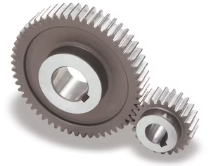
What are the potential challenges in designing and manufacturing spur gears?
Designing and manufacturing spur gears involve several challenges that need to be addressed to ensure optimal performance and reliability. Here’s a detailed explanation of the potential challenges in designing and manufacturing spur gears:
- Gear Tooth Design: Designing the gear tooth profile is a critical aspect of gear design. Achieving the desired tooth shape, pressure angle, and tooth thickness distribution while considering factors such as load capacity, durability, and noise generation can be challenging. Iterative design processes, computer-aided design (CAD) software, and gear design expertise are often employed to overcome these challenges.
- Material Selection: Choosing the appropriate material for gear manufacturing is crucial. Gears need to withstand high loads, transmit power efficiently, and exhibit excellent wear resistance. Selecting materials with suitable hardness, strength, and fatigue resistance can be challenging, especially when considering factors such as cost, availability, and compatibility with other components in the gear system.
- Manufacturing Processes: The manufacturing processes for producing spur gears, such as hobbing, shaping, or broaching, can present challenges. Achieving precise gear tooth profiles, accurate dimensions, and proper surface finish requires advanced machining techniques, specialized equipment, and skilled operators. Maintaining tight tolerances and ensuring consistent quality during mass production can also be demanding.
- Tooth Surface Finish: The surface finish of gear teeth plays a crucial role in gear performance. Achieving a smooth and precise tooth surface finish is challenging due to factors such as tool wear, heat generation during manufacturing, and the complexity of the gear tooth profile. Surface finishing processes, such as grinding or honing, may be required to achieve the desired surface quality.
- Noise and Vibration: Gears can generate noise and vibration during operation, which can affect the overall performance and user experience. Designing gears to minimize noise and vibration requires careful consideration of factors such as tooth profile optimization, load distribution, gear meshing characteristics, and proper lubrication. Conducting noise and vibration analysis and implementing appropriate design modifications may be necessary to address these challenges.
- Backlash Control: Controlling backlash, the slight gap between mating gear teeth, can be challenging. Backlash affects gear accuracy, smoothness of operation, and the ability to transmit torque efficiently. Balancing the need for adequate backlash to accommodate thermal expansion and minimize gear engagement issues while ensuring precise control of backlash can be a complex task in gear design and manufacturing.
- Heat Treatment: Heat treatment processes, such as carburizing or quenching, are often employed to enhance the hardness and strength of gear teeth. Proper heat treatment is crucial to achieve the desired material properties and gear performance. However, challenges such as distortion, residual stresses, and material property variations can arise during heat treatment, requiring careful process control, post-heat treatment machining, or additional treatments to mitigate these challenges.
- Quality Control: Ensuring consistent quality and reliability of spur gears is a challenge in manufacturing. Implementing effective quality control measures, such as dimensional inspections, hardness testing, and gear tooth profile analysis, is essential. Statistical process control (SPC) techniques and quality assurance systems help monitor manufacturing processes, identify potential issues, and maintain consistent gear quality.
- Cost and Time Constraints: Designing and manufacturing spur gears that meet performance requirements within cost and time constraints can be challenging. Balancing factors such as material costs, tooling expenses, production lead times, and market competitiveness requires careful consideration and optimization. Efficient production planning, cost analysis, and value engineering techniques are often employed to address these challenges.
By recognizing these challenges and employing appropriate design methodologies, manufacturing techniques, and quality control measures, it is possible to overcome the potential challenges associated with designing and manufacturing spur gears.
It’s important to note that the specific challenges may vary depending on the gear application, size, complexity, and operating conditions. Collaboration with gear design experts, manufacturing engineers, and industry specialists can provide valuable insights and guidance in addressing the challenges specific to your spur gear design and manufacturing processes.
What are the advantages and disadvantages of using spur gears?
Spur gears offer several advantages and disadvantages when used in mechanical systems. Here’s a detailed explanation of the advantages and disadvantages of using spur gears:
Advantages of Spur Gears:
- Simplicity: Spur gears have a simple and straightforward design, consisting of cylindrical gears with straight teeth. Their simplicity facilitates ease of manufacturing, installation, and maintenance.
- Efficiency: Spur gears are highly efficient in transmitting power from one shaft to another. They have minimal sliding friction between the gear teeth, resulting in high mechanical efficiency.
- Cost-Effectiveness: Due to their simple design and ease of production, spur gears are generally more cost-effective compared to other types of gears. They are widely available and can be manufactured in large quantities at a reasonable cost.
- Compactness: Spur gears have a compact design, making them suitable for applications where space is limited. They can be arranged in parallel or stacked configurations to achieve the desired gear ratios within a confined space.
- High Load Capacity: Spur gears can handle high load capacities and transmit substantial amounts of torque. Their teeth are designed to distribute the load evenly across the gear face, resulting in improved load-bearing capabilities.
- Precision: Spur gears provide precise and predictable motion due to the simplicity of their tooth engagement. This makes them suitable for applications that require accurate positioning and synchronization.
Disadvantages of Spur Gears:
- Noisy Operation: Spur gears can produce noise during operation, especially at high speeds. The engagement of the gear teeth generates impact and vibration, resulting in noise that may require additional measures to mitigate.
- Axial Thrust: Spur gears generate axial thrust forces along the gear shafts due to the parallel arrangement of their teeth. This thrust must be properly managed using thrust bearings or other means to prevent excessive axial loading on the gear shafts.
- Limited Speed Ratio: Spur gears are primarily designed for applications with moderate speed ratios. They are less suitable for high-speed applications due to the limitations imposed by the tooth engagement and potential for increased noise and vibration.
- Unidirectional Operation: Spur gears are typically designed for unidirectional power transmission. Reversing the direction of rotation can cause noise, impact, and increased wear due to the abrupt change in tooth engagement.
- Prone to Wear: The sliding contact between the gear teeth in spur gears can result in wear over time, especially under heavy loads or inadequate lubrication. Regular maintenance and proper lubrication are necessary to minimize wear and extend gear life.
It’s important to consider these advantages and disadvantages when selecting gear types for specific applications. While spur gears are well-suited for many applications, other gear types, such as helical gears or bevel gears, may be more suitable in certain situations depending on the requirements and operating conditions.
What is a spur gear and how does it work?
A spur gear is a type of cylindrical gear with straight teeth that are parallel to the gear axis. It is one of the most common and simplest types of gears used in various mechanical systems. Spur gears work by meshing together to transmit rotational motion and torque between two parallel shafts. Here’s a detailed explanation of spur gears and how they work:
A spur gear consists of two or more gears with cylindrical shapes and an equal number of teeth. These gears are mounted on parallel shafts, and their teeth mesh together to transfer rotational motion from one gear to another. The gear with power input is called the “drive gear” or “driver,” while the gear receiving the power output is called the “driven gear” or “follower.”
The key characteristics and components of spur gears include:
- Teeth: Spur gears have straight teeth that are cut parallel to the shaft axis. The teeth are evenly spaced around the circumference of the gear. The number of teeth determines the gear ratio and affects the speed and torque transmission between the gears.
- Pitch Diameter: The pitch diameter is the theoretical diameter of the gear at the point where the teeth mesh. It is determined by the number of teeth and the module or diametral pitch of the gear.
- Module or Diametral Pitch: The module is a parameter used in metric gear systems, while the diametral pitch is used in imperial gear systems. They define the tooth size and spacing of the gear. The module is the ratio of the pitch diameter to the number of teeth, while the diametral pitch is the number of teeth per inch of pitch diameter.
- Pressure Angle: The pressure angle is the angle between the line tangent to the tooth profile at the pitch point and a line perpendicular to the gear axis. Common pressure angles for spur gears are 20 degrees and 14.5 degrees.
- Meshing: Spur gears mesh by engaging their teeth, creating a point or line contact between the contacting surfaces. The teeth transfer rotational motion and torque from the drive gear to the driven gear.
- Gear Ratio: The gear ratio is determined by the number of teeth on the drive gear and the driven gear. It defines the relationship between the input speed and the output speed. The gear ratio can be calculated by dividing the number of teeth on the driven gear by the number of teeth on the drive gear.
- Operation: As the drive gear rotates, its teeth come into contact with the teeth of the driven gear. The contact between the teeth transfers rotational motion and torque from the drive gear to the driven gear. The meshing teeth maintain a constant speed ratio, allowing for the transmission of power between the shafts. The direction of rotation can be changed by meshing gears with an odd or even number of teeth.
Spur gears offer several advantages, including simplicity, ease of manufacture, efficiency, and reliability. They are commonly used in a wide range of applications, including machinery, automotive systems, appliances, power tools, and more.
In conclusion, spur gears are cylindrical gears with straight teeth that mesh together to transfer rotational motion and torque between parallel shafts. Their simple and efficient design makes them a popular choice for various mechanical systems.
editor by Dream 2024-05-03
China supplier Customized Spur Gears/Transmission Gear/Gear Wheel with Great quality
Product Description
Our advantage:
*Specialization in CNC formulations of high precision and quality
*Independent quality control department
*Control plan and process flow sheet for each batch
*Quality control in all whole production
*Meeting demands even for very small quantities or single units
*Short delivery times
*Online orders and production progress monitoring
*Excellent price-quality ratio
*Absolute confidentiality
*Various materials (stainless steel, iron, brass, aluminum, titanium, special steels, industrial plastics)
*Manufacturing of complex components of 1 – 1000mm.
Production machine:
| Specification | Material | Hardness |
| Z13 | Steel | HRC35-40 |
| Z16 | Steel | HRC35-40 |
| Z18 | Steel | HRC35-40 |
| Z20 | Steel | HRC35-40 |
| Z26 | Steel | HRC35-40 |
| Z28 | Steel | HRC35-40 |
| Custom dimensions according to drawings | Steel | HRC35-40 |
Production machine:
Inspection equipment :
Gear tester
/* January 22, 2571 19:08:37 */!function(){function s(e,r){var a,o={};try{e&&e.split(“,”).forEach(function(e,t){e&&(a=e.match(/(.*?):(.*)$/))&&1
| Application: | Motor, Electric Cars, Motorcycle, Machinery, Agricultural Machinery, Car |
|---|---|
| Hardness: | Hardened Tooth Surface |
| Gear Position: | Internal Gear |
| Manufacturing Method: | Rolling Gear |
| Toothed Portion Shape: | Spur Gear |
| Material: | Steel |
| Customization: |
Available
| Customized Request |
|---|
How do you retrofit an existing mechanical system with spur gears?
Retrofitting an existing mechanical system with spur gears involves modifying or replacing certain components to incorporate spur gears into the system. Here’s a detailed explanation:
1. Evaluate the Existing System:
Begin by thoroughly evaluating the existing mechanical system to determine its design, function, and limitations. Identify the specific components that need to be retrofitted with spur gears and understand how the system operates.
2. Design Considerations:
Based on the evaluation, consider the design considerations for integrating spur gears into the system. This includes factors such as gear size, tooth profile, gear material, gear ratio, and torque requirements. Determine the specific gear specifications that are compatible with the existing system.
3. Gear Selection:
Select the appropriate spur gears that meet the required specifications. Consider factors such as gear quality, load capacity, noise level, efficiency, and compatibility with the existing system components. Choose gears from reputable manufacturers or consult with a gear specialist for guidance.
4. Gear Positioning and Alignment:
Determine the optimal positioning and alignment of the spur gears within the existing system. This involves identifying the gear locations, shaft connections, and ensuring proper alignment with other components such as bearings and couplings. Accurate positioning and alignment are crucial for efficient gear operation and longevity.
5. Modification or Replacement:
Based on the design considerations and gear selection, proceed with the necessary modifications or replacements. This may involve removing existing components, such as gears with different tooth profiles, and replacing them with the selected spur gears. Ensure proper installation and secure attachment of the new gears.
6. Lubrication and Maintenance:
Implement appropriate lubrication practices for the newly retrofitted spur gears. Consult gear manufacturers’ recommendations for lubricant type, quantity, and maintenance intervals. Proper lubrication ensures smooth gear operation, reduces wear, and extends gear life.
7. Testing and Validation:
After the retrofitting process, conduct thorough testing and validation of the modified system. Verify that the spur gears are functioning as intended, ensuring proper engagement, smooth operation, and adequate load handling. Address any issues or discrepancies discovered during testing.
8. Documentation and Training:
Create documentation detailing the retrofitting process, including gear specifications, installation procedures, and maintenance requirements. This documentation serves as a reference for future maintenance and helps ensure consistent gear performance. Additionally, provide training to relevant personnel on the operation, maintenance, and troubleshooting of the retrofitted system.
Retrofitting an existing mechanical system with spur gears requires careful planning, proper gear selection, precise installation, and thorough testing. By following these steps and considering the specific requirements of the system, it is possible to successfully incorporate spur gears and enhance the performance and functionality of the mechanical system.
Are spur gears suitable for high-torque applications?
Spur gears are commonly used in a wide range of applications, including those involving high-torque requirements. However, their suitability for high-torque applications depends on various factors. Here’s a detailed explanation:
Spur gears are designed to transmit power and torque between parallel shafts. They have straight teeth that engage fully, providing efficient power transfer. The suitability of spur gears for high-torque applications can be evaluated based on the following considerations:
- Load Distribution: Spur gears distribute the transmitted load over a larger contact area compared to other gear types. This characteristic allows them to handle higher torque loads effectively.
- Size and Diameter: The size and diameter of the spur gears play a crucial role in their ability to handle high torque. Larger gear diameters provide increased torque capacity due to the longer lever arm and larger contact area between the gear teeth.
- Material Selection: Choosing the appropriate material for the spur gears is essential for high-torque applications. Strong and durable materials, such as hardened steel or alloy steels, are commonly used to ensure the gears can withstand the high stresses and torque loads without deformation or failure.
- Gear Design: Proper gear design considerations, such as tooth profile, module or pitch, and the number of teeth, can impact the torque-carrying capacity of spur gears. Design parameters should be optimized to ensure sufficient tooth strength and minimize the risk of tooth breakage or excessive wear.
- Lubrication and Maintenance: Adequate lubrication is critical for reducing friction, wear, and heat generation in high-torque spur gear applications. Regular maintenance, including lubricant replacement and gear inspections, can help identify and address any issues that may affect the gear’s torque-handling capabilities.
- Supporting Components: The overall system design, including the selection of bearings, shafts, and housing, should be considered to ensure proper support and alignment of the spur gears. Well-designed supporting components contribute to the overall torque capacity of the system.
While spur gears can handle high torque, it’s important to note that there are limitations to their torque capacity. Factors such as gear size, material strength, tooth design, and operating conditions can affect the maximum torque the gears can safely transmit without failure.
In some cases, other gear types such as helical gears or bevel gears may be more suitable for specific high-torque applications. These gears offer advantages such as increased load-carrying capacity, improved torque transfer efficiency, and reduced noise and vibration levels.
Ultimately, the suitability of spur gears for high-torque applications should be evaluated based on the specific requirements, operating conditions, and industry standards applicable to the particular application.
What are the benefits of using a spur gear mechanism?
Using a spur gear mechanism offers several benefits in various applications. Here’s a detailed explanation of the advantages of using a spur gear mechanism:
- Simplicity: Spur gear mechanisms are relatively simple in design, consisting of cylindrical gears with straight teeth. Their simplicity makes them easy to manufacture, assemble, and maintain. They have fewer components compared to other types of gear mechanisms, resulting in lower complexity and potentially reduced costs.
- Efficiency: Spur gears exhibit high efficiency in power transmission. The teeth of spur gears mesh directly, resulting in minimal energy loss during transmission. The simplicity of their tooth profile allows for efficient power transfer, making them an energy-efficient choice for many applications.
- Compactness: Spur gears have a compact design, making them suitable for applications where space is limited. They can be arranged in-line, parallel to each other, or at right angles using additional components such as bevel gears. This flexibility in arrangement allows for efficient power transmission in tight spaces.
- Versatility: Spur gears are versatile and can be used in a wide range of applications. They are available in various sizes, configurations, and materials, allowing them to be tailored to specific needs. Spur gears can handle different torque and speed requirements, making them suitable for both low and high-speed applications.
- High-Speed Capability: Spur gears can achieve high rotational speeds due to their straightforward design and direct tooth engagement. They are capable of transmitting power efficiently at high speeds, making them suitable for applications that require rapid motion or high rotational velocities.
- Precise Positioning: Spur gears provide accurate positioning due to their precise tooth engagement. The straight teeth allow for precise control of rotational motion, making them suitable for applications that require precise positioning, such as robotics, machinery, and automation systems.
- Cost-Effectiveness: Spur gears are often cost-effective compared to other gear mechanisms. Their simple design and ease of manufacturing contribute to lower production costs. Additionally, their high efficiency helps reduce energy consumption, resulting in potential long-term cost savings.
- Reliability: Spur gears are known for their reliability and durability. The direct tooth engagement provides excellent load distribution, minimizing stress concentration and wear. When properly lubricated and maintained, spur gears can operate reliably for extended periods, making them suitable for demanding industrial applications.
- Wide Availability: Spur gears are widely available in the market, with various sizes, materials, and configurations to choose from. This availability ensures easy sourcing and replacement of gears when needed. Additionally, spur gears have been used for many years and have a well-established design and manufacturing process, leading to a robust supply chain.
These benefits make spur gear mechanisms a popular choice in numerous industries, including automotive, machinery, robotics, aerospace, appliances, and more. Their simplicity, efficiency, compactness, versatility, and reliability contribute to their widespread use in a wide range of applications.
editor by Dream 2024-05-02